

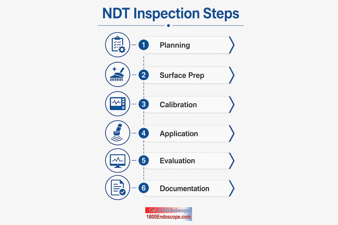
Step-by-step NDT inspection is the structured process by which trained technicians detect flaws in materials and structures without causing damage, confirming quality and safety across industrial applications. The industry-standard approach follows a 6-stage process: planning, surface preparation, equipment calibration, method application, evaluation against acceptance criteria, and reporting. Standards bodies including ASME, API, and AWS define the acceptance criteria technicians apply at each stage. Skipping or compressing any stage does not save time. It creates liability, missed defects, and failed audits.
What are the essential prerequisites and planning steps before starting an NDT inspection?
Planning is the stage that determines whether an inspection produces usable results or ambiguous data. The UK Health and Safety Executive requires clear specifications of plant items and anticipated damage mechanisms before any NDT work begins. Treating NDT like a high-stakes procurement, where you define exactly what you need before you buy, prevents vague results that satisfy no one.
Effective planning covers these core activities:
- Define the inspection scope. Identify which components require inspection, what defect types are anticipated (cracks, porosity, corrosion, delamination), and what the acceptance criteria are per the applicable standard (ASME Section V, API 570, EN ISO 17636).
- Review prior records. Pull engineering drawings, previous inspection reports, and maintenance history. Defects rarely appear in isolation. Prior findings predict where to look next.
- Select the right NDT method. Method selection depends on defect type, material, and component geometry. Surface-breaking cracks suit liquid penetrant or magnetic particle testing. Subsurface flaws require ultrasonic or radiographic methods. Complex geometries often need two methods for full coverage.
- Assess access and safety. Confirm scaffolding, confined space permits, radiation exclusion zones, and personal protective equipment requirements before mobilizing.
- Assign qualified personnel. NDT technicians must hold certifications appropriate to the method and level required, per ASNT SNT-TC-1A or ISO 9712.
Pro Tip: Write a one-page inspection brief for every job. It forces clarity on scope, method, and acceptance criteria before anyone touches the component. Teams that skip this step spend twice as long resolving ambiguous findings in the field.
How to prepare the surface and environment to maximize inspection accuracy?

Poor surface preparation is the leading cause of false negatives in NDT, particularly in liquid penetrant and magnetic particle testing. Paint, scale, grease, and rust physically block penetrant entry into cracks and scatter magnetic flux away from defect locations. The time spent on preparation directly determines the reliability of every result that follows.
Surface preparation requirements vary by method:
- Liquid penetrant testing (PT): Remove all coatings, oils, and oxides from the test surface. Solvent cleaning or abrasive blasting is standard. The surface must be dry before penetrant application.
- Magnetic particle testing (MT): Remove loose scale and heavy coatings. Thin coatings up to 50 micrometers are generally acceptable, but verify against the applicable procedure.
- Ultrasonic testing (UT): Apply a coupling agent (gel, oil, or water) to eliminate air gaps between the transducer and the surface. A rough surface reduces signal quality significantly.
- Radiographic testing (RT): Clean the surface to remove debris that could appear as false indications on the film or digital detector.
Environmental controls matter equally. Penetrant dwell times range from 5 to 60 minutes depending on material and defect type. Temperature outside the 10°C to 52°C range invalidates most penetrant procedures. Fluorescent PT requires a minimum UV-A irradiance of 10 W/m², while color contrast PT requires at least 500 lux of white light.
Pro Tip: Photograph the surface condition before and after preparation. This documentation protects you if a client disputes findings and provides a baseline for future inspections of the same component.
What equipment setup and calibration steps ensure reliable NDT inspection results?
Traceable equipment calibration before each inspection session is legally and technically mandatory. Uncalibrated equipment invalidates the inspection entirely. Insurers and regulators treat undocumented calibration the same way they treat no calibration at all.
Follow these calibration steps before applying any method:
- Verify calibration currency. Check that all instruments carry current calibration certificates traceable to a national metrology standard (NIST in the United States). Expired certificates require recalibration before use.
- Perform a system check with reference standards. For ultrasonic testing, use calibration blocks (IIW Type 1 or ASTM E127) to set velocity, zero offset, and sensitivity. For radiography, place image quality indicators (IQIs or penetrameters) on the component to confirm image resolution meets the required sensitivity.
- Verify magnetic field strength for MT. Use a Hall-effect gaussmeter or a field indicator to confirm minimum tangential field strength of 2 kA/m across the inspection zone.
- Check lighting equipment. Calibrate UV-A lamps and white light meters against known references. Lamp intensity degrades with use. A lamp that passed calibration six months ago may not meet current requirements.
- Document everything. Record instrument serial numbers, calibration block IDs, measured values, and the technician's name and certification level. This record travels with the inspection report.
Pro Tip: Keep a dedicated calibration log for each piece of equipment. A single page per instrument, updated at every use, takes two minutes and has saved teams from failed audits that would have required re-inspection of entire plant sections.
For light source verification, the calibration process for inspection lighting follows the same traceability principles that apply to all NDT equipment.
How do you execute the NDT method and detect defects accurately?
Method execution is where preparation and calibration pay off. Each technique has a defined sequence that must be followed without improvisation.
Magnetic particle testing
- Magnetize the component using the appropriate technique (yoke, prod, coil, or central conductor) with the field oriented perpendicular to the anticipated crack direction.
- Apply dry or wet magnetic particles during or immediately after magnetization, depending on the procedure.
- Inspect under adequate lighting. Fluorescent MT requires UV-A illumination; visible MT requires white light at minimum 500 lux.
- Rotate the field orientation by 90 degrees and repeat to catch cracks running parallel to the first field direction.
Liquid penetrant testing
- Apply penetrant to the clean, dry surface and allow the full dwell time specified in the procedure (typically 10 to 30 minutes for most structural steels).
- Remove excess penetrant using the specified method (solvent wipe, water wash, or emulsifier). Over-washing removes penetrant from shallow defects.
- Apply developer and allow development time equal to at least half the dwell time.
- Inspect under the required lighting conditions within the time window specified in the procedure.
Ultrasonic testing
Scan the component in overlapping passes, with each pass covering at least 10% of the previous scan width. Angle beam probes (45°, 60°, or 70°) detect planar defects like cracks and lack of fusion in welds. Straight beam probes detect laminations and thickness loss. Record all indications that exceed the reference level before evaluating them against acceptance criteria.
Visual testing with borescopes
Visual testing (VT) is the most widely applied NDT method and the foundation of any endoscopic weld inspection program. For inaccessible areas such as pipe interiors, turbine blades, or heat exchanger tubes, a video borescope provides direct visual access. Inspect systematically, covering the full surface area in a defined pattern. Record video or still images of all indications for the report.
How to interpret, evaluate, and document inspection results according to standards?
Evaluation separates a technician from a scanner. Every indication requires a decision: is it relevant, non-relevant, or a false indication caused by geometry or surface condition?
The evaluation process follows this sequence:
- Classify the indication. A relevant indication originates from a discontinuity. A non-relevant indication comes from geometry (threads, knurling, press fits). A false indication comes from poor technique or contamination.
- Measure and characterize. Record the location, orientation, length, depth (for UT), and type of each relevant indication.
- Apply acceptance criteria. Compare findings against the applicable standard. ASME B31.3 sets limits for weld defects in process piping. API 653 governs storage tank inspection. AWS D1.1 covers structural steel welds. An indication that exceeds the acceptance limit requires disposition: repair, replace, or engineering fitness-for-service assessment.
- Prepare the inspection report. Inspection reports must include component identification, method and technique parameters, calibration records, all indications found, their classifications, and the final disposition. Reports serve maintenance planning, compliance audits, insurance claims, and legal records for years after the inspection.
Pro Tip: Use standardized report templates aligned to the applicable standard. A report that matches the format auditors expect gets reviewed faster and raises fewer questions.
The NDT inspection checklist approach helps technicians confirm every documentation requirement is met before closing out an inspection package.
Inspection reports serve long-term legal and safety roles that extend well beyond the immediate maintenance cycle. A report from a pressure vessel inspection conducted today may be the critical document in a regulatory review a decade from now.
Key Takeaways
A complete NDT inspection requires six defined stages executed in sequence, with no stage optional or compressible without risking invalid results, missed defects, or regulatory failure.
| Point | Details |
|---|---|
| Follow the 6-stage process | Planning, prep, calibration, application, evaluation, and reporting must all be completed in order. |
| Surface preparation drives accuracy | Removing paint, scale, and grease before testing is the single biggest factor in avoiding false negatives. |
| Calibration must be traceable | Document instrument serial numbers and reference standards used; undocumented calibration invalidates the inspection. |
| Match the method to the defect | Surface defects suit PT or MT; subsurface flaws require UT or RT; complex geometry often needs two methods. |
| Reports have long-term legal value | Retain inspection reports with full calibration records for audits, insurance, and regulatory review. |
What I've learned from watching NDT inspections fail
The most common failure mode in NDT is not a missed defect. It is a missed step in the procedure. I have reviewed inspection packages where the technician clearly found the right indications but evaluated them against the wrong acceptance criteria because the procedure referenced an outdated standard revision. The defect was there. The call was wrong. The component went back into service.
Site-specific, approved NDT procedures exist precisely to prevent this. Generic procedures downloaded from the internet are a liability. They do not account for your specific material grades, your weld joint configurations, or the regulatory jurisdiction you operate in. Every procedure must be reviewed and approved for the specific job before work starts.
Surface preparation deserves more time than most teams give it. The time invested in thorough surface preparation equals or exceeds the inspection phase itself when you factor in the cost of re-inspection caused by false negatives. A technician who spends 45 minutes preparing a weld for magnetic particle testing and 15 minutes scanning it has the right ratio. The reverse is a recipe for missed cracks.
Combining methods is not a sign of uncertainty. It is a sign of competence. Ultrasonic testing finds volumetric defects that magnetic particle testing cannot detect. Magnetic particle testing finds surface-breaking cracks that UT can miss at shallow angles. Using both on a critical weld is not redundancy. It is complete coverage.
— Endoscope
NDT inspection tools from 1800endoscope
Industrial technicians need portable, reliable visual inspection tools that fit into a structured NDT workflow without adding complexity.
1800endoscope carries a full range of industrial borescopes and videoscopes built for the demanding conditions of plant and field inspections. These systems give technicians direct visual access to pipe interiors, weld roots, heat exchanger tubes, and other confined areas that no other NDT method can reach without disassembly. HD video recording and on-board storage mean your visual testing findings go directly into the inspection report with no extra steps. For technicians who need a portable, self-contained system, the 6mm airway inspection videoscope delivers monitor-direct viewing with SD card recording at a price point that works for field teams. Contact 1800endoscope to match the right tool to your inspection requirements.
FAQ
What is the standard NDT inspection process?
The standard NDT inspection process follows six stages: planning, surface preparation, equipment calibration, method application, evaluation against acceptance criteria, and reporting. Skipping any stage risks invalid results or missed defects.
How do I choose the right NDT method for my application?
Method selection depends on defect type, material, and component geometry. Surface-breaking defects suit liquid penetrant or magnetic particle testing; subsurface defects require ultrasonic or radiographic methods. Complex components often need two methods for complete coverage.
Why does surface preparation matter so much in NDT?
Poor surface preparation is the leading cause of false negatives in NDT. Paint, grease, and scale physically block penetrant entry into cracks and scatter magnetic flux, causing real defects to go undetected.
How long must NDT inspection reports be retained?
Inspection reports must be retained for years after the inspection to support maintenance planning, compliance audits, insurance claims, and legal review. The specific retention period depends on the applicable regulatory standard and jurisdiction.
What calibration is required before an NDT inspection?
All instruments must carry current calibration certificates traceable to a recognized national standard such as NIST. For magnetic particle testing, field strength must be verified at a minimum of 2 kA/m using a Hall-effect gaussmeter or field indicator before scanning begins.