
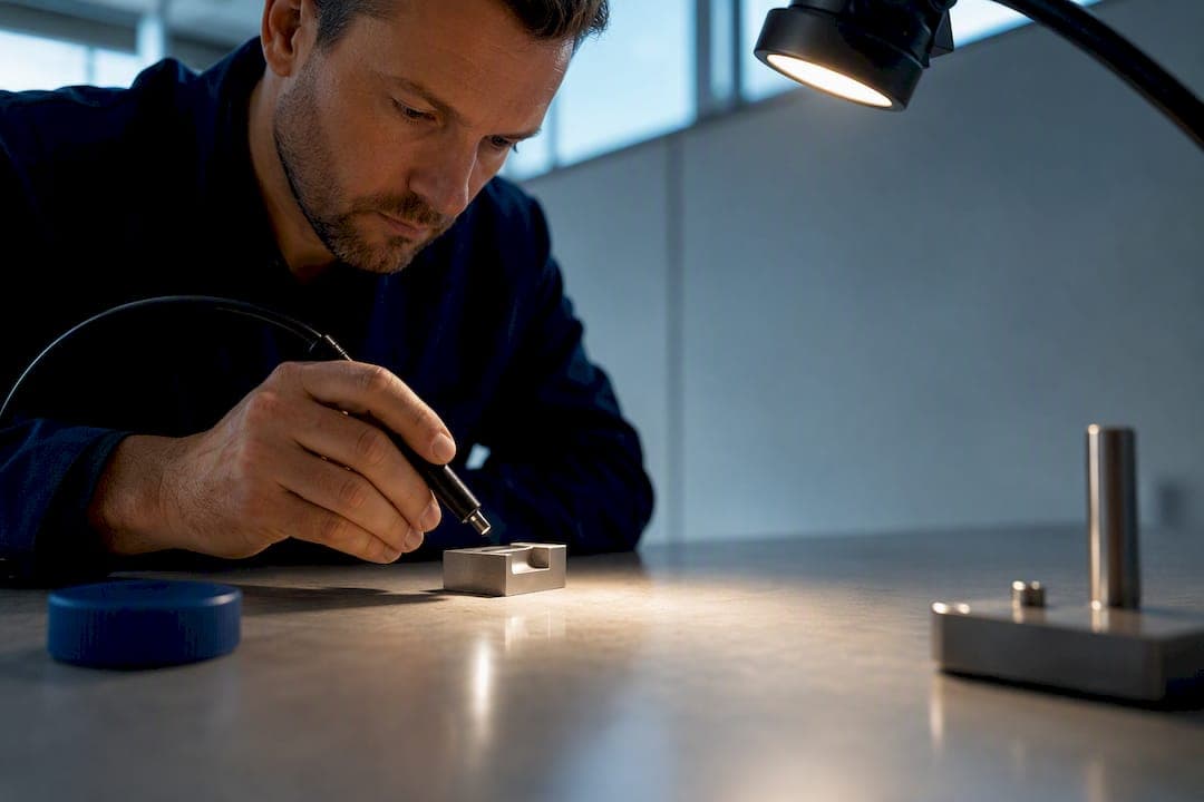
A measurement videoscope is a video borescope that outputs quantifiable data, not just an image. It uses stereo optics, structured light, or a calibrated single-camera system to convert what the probe sees into numbers: pit depth, crack width, material loss, distance between two points. Choose one over a standard inspection videoscope only when the job requires a documented figure, an engineering threshold, or a trend you'll track over time. If you just need to confirm whether damage exists, a standard videoscope is cheaper and faster.
TL;DR:
- Accurate measurement videoscopes require proper calibration and maintenance, as their reliability depends more on discipline than hardware resolution alone.
- The choice between stereo, structured-light, or single-camera systems depends on application needs, with calibration quality and position accuracy being critical factors.
- Probe diameter, working distance, and illumination control are key considerations that influence measurement precision and suitability for specific inspection tasks.
- Consistent workflows, including calibration verification and capturing multiple readings, significantly improve repeatability and measurement reliability.
- Prioritizing calibration procedures and proper workflow discipline ensures measurement accuracy far more than hardware specifications or resolution alone.
Table of Contents
- Key features and types of measurement videoscopes
- How measurement methods work and what accuracy to expect
- How to choose a measurement videoscope: a selection checklist
- Setting up a repeatable measurement workflow
- Where to find measurement-ready systems and support
- Why measurement-first thinking beats spec-sheet shopping
- Get set up with the right measurement videoscope
- Sources
Key features and types of measurement videoscopes
A videoscope puts a miniature camera on the end of a flexible or rigid tube, and everything downstream of that camera determines whether it can measure anything useful. The probe itself comes in two general families: flexible microprobes, often 4mm to 6mm in diameter, that snake through tight bores and manifolds, and small-diameter rigid probes built for straight-line access where stiffness improves image stability. A softer probe gets into more places; a rigid one holds a steadier frame for capture, which matters more than people expect once you're trying to measure something.
Sensor resolution and pixel size set the floor on measurable detail. A higher-resolution sensor resolves finer crack widths and smaller pits, but resolution alone doesn't help if the field of view and working distance don't match your access geometry. A wide FOV shows more context around a defect; a narrow one gets you closer to the surface for finer detail. Both trade off against each other, so match the spec sheet to the actual bore diameter and inspection distance you'll be working in, not the number that looks most impressive.
Illumination and tip design matter more in measurement work than in general visual inspection, because glare and shadow distort a measurement reading in ways they'd never distort a pass/fail visual call. Look for:
- Adjustable LED rings that let you dial brightness down on reflective metal
- Polarizing or anti-glare tip adapters for wet or oily surfaces
- Working-channel accessories that support cleaning or repositioning without removing the probe
The control unit is where the measurement software lives, along with mount points and, on higher-end systems, vibration isolation that keeps a handheld capture from blurring at the pixel level a measurement needs. System categories break into three groups: stereo or 3D-capable units that use two optical paths to derive depth, structured-light systems that project a pattern onto the surface to reconstruct geometry, and calibrated single-camera systems that estimate distance through known reference points. Some commercial 3D stereo measurement videoscopes bundle all of this into one control unit with integrated software, which is worth understanding even if you're comparing capability categories rather than specific brands.
How measurement methods work and what accuracy to expect
Stereo imaging works the way human depth perception does: two camera paths capture the same surface from slightly different angles, and the software triangulates the offset into a depth map. Structured-light systems instead project a known pattern, usually a grid or line array, onto the surface and read how that pattern distorts to reconstruct height and depth. Both approaches need a stable, well-lit view of the target to produce a clean result. A single-camera calibrated system skips the geometry math and instead references a known object size in frame to scale a point-to-point measurement, which is simpler but more sensitive to viewing angle error.
Five variables drive how accurate any of these methods actually turn out in the field:
- Distance and angle between the probe tip and the surface
- Illumination evenness across the measured area
- Surface reflectivity and texture
- Probe motion or vibration during capture
- Calibration quality and how recently it was verified
Manufacturer accuracy claims usually appear as a tolerance band, something like ±0.001 inch or ±0.05mm, and that number is only meaningful under the conditions it was tested at. Ask what surface, distance, and geometry the spec was validated against before you assume it applies to your application, since accuracy specs are conditional rather than universal guarantees.
Measurement outputs typically fall into four types: depth (how deep a pit or gouge runs), profile (the surface contour across a defect), area (surface coverage of corrosion or erosion), and point-to-point (straight-line distance between two chosen locations). Depth and point-to-point drive most pass/fail engineering decisions; profile and area matter more for tracking degradation over successive inspections.
How to choose a measurement videoscope: a selection checklist
Work through these in order, because each answer narrows the next decision.
- Define the required accuracy first. If your engineering threshold demands ±0.002 inch, that rules out lower-tier single-camera systems before you look at anything else.
- Map access geometry to probe diameter and working distance. Measure your smallest access point and required reach, then find probes with margin, not a tight fit.
- Confirm field of view and viewing angle match the defect type. A wide viewing angle suits general surface scanning; a narrow one suits fine crack detail.
- Check software output formats. You need measurement export, not just image capture, and ideally a traceable calibration report attached to each file.
- Verify environmental ratings and battery life against your actual site conditions, not a lab spec sheet.
- Confirm calibration service availability before you buy, not after the unit is already six months out of certification.
- Ask the vendor for calibration certificates, sample measurement files, and in-field repeatability data on materials similar to yours, rather than accepting a single tolerance number at face value.
Skipping step one is the most common mistake. Technicians buy a mid-tier stereo system because it looks capable, then discover it can't hit the tolerance a client's spec calls for.
Setting up a repeatable measurement workflow
Consistent results come from a repeatable sequence, not from a more expensive unit. Run through this before every measurement session:
- Inspect the probe for scratches, tip damage, or debris on the optics, and mount the control unit securely so it won't shift mid-capture.
- Charge the unit and confirm firmware and software versions match what your calibration certificate was issued against.
- Calibrate against a traceable reference target, and document the ambient conditions, distance, and angle used during calibration.
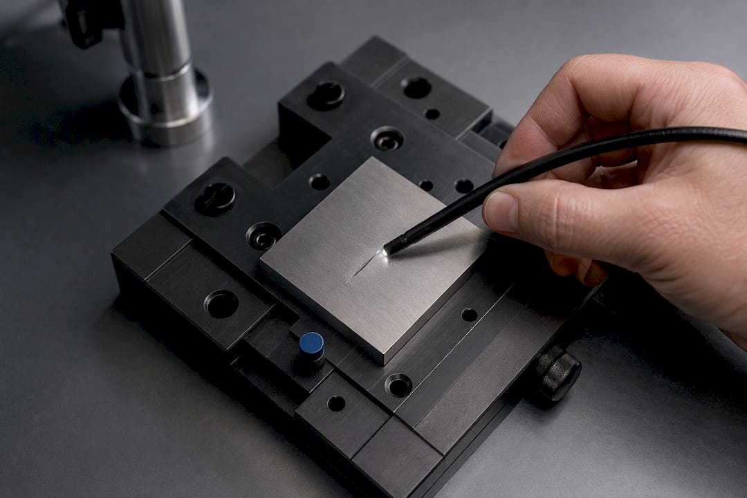
- Capture the measurement, keeping the probe as steady as possible or supported by a mount, aiming for a perpendicular view of the surface, and taking multiple captures rather than relying on one frame.
- Control lighting to minimize glare on reflective or wet surfaces before locking in the reading.
- Run a known-reference repeatability check against a reference feature of known dimension before you trust the session's readings.
- Export the raw measurement file, embed reference markers in the image, and save measurement metadata alongside the image for later trend comparison.
Minimizing probe motion during capture is the single biggest lever most technicians underuse, since even a supported or rigid mount during 3D capture improves repeatability more than upgrading sensor resolution does.
Pro Tip: Take three captures of the same defect from slightly different angles before you close out an inspection. If the readings drift more than your tolerance band allows, the problem is almost always probe motion or glare, not the instrument.
Where to find measurement-ready systems and support
1800endoscope carries portable, measurement-capable videoscopes built with HD recording, wireless connectivity, and field-ready control units suited to industrial and veterinary inspection work. The full catalog covers NDT borescopes, accessories, and light sources for technicians who need to match a specific probe diameter or working distance to a job.
- Product specs and probe diameter options: catalog
- Application guidance by inspection type: videoscope applications guide
- Recording and file-management practices: optimizing video recording
Why measurement-first thinking beats spec-sheet shopping
Most buying guides treat measurement videoscopes like a spec race: highest resolution wins, smallest probe wins, most megapixels wins. That's backward. The variable that actually determines whether your readings hold up under scrutiny is calibration discipline, not sensor count. A mid-resolution stereo unit with a documented calibration routine and a technician who checks repeatability before every session will outperform a flagship unit run carelessly.
The conventional advice skips this almost entirely. It talks about accuracy tolerances as if they're fixed properties of the hardware, when they're actually conditional on distance, angle, lighting, and how recently the unit was calibrated against a traceable target. A ±0.001 inch spec means nothing if nobody in your shop can say when the last calibration happened.
Prioritize the workflow before the hardware. Build a calibration and repeatability check into every session, document it, and only then worry about whether you need stereo, structured light, or a calibrated single-camera system. The instrument matters less than the discipline around it.
— Endoscope
Get set up with the right measurement videoscope
If you've made it this far, you already know a measurement videoscope earns its price only when the job demands numbers, not just a look. 1800endoscope sells the equipment that makes that distinction workable in the field: portable, measurement-capable systems built for technicians who need a documented reading, not a guess.
The portable SD card video inspection system gives you a compact, affordable option for airway and confined-space inspection work where portability matters as much as image quality. For field crews who need USB recording alongside a rugged monitor setup, the field scope videoscope covers that use case directly. Browse the full catalog to compare probe diameters, working distances, and accessory options against the checklist you just read, and reach out through the FAQ and inspection procedures page if you need help matching a system to your specific access geometry before you order.
Sources
- Borescope
- How to Perform 3D Surface Analysis Using a Videoscope
- Videoscopes Selection Guide: Types, Features, Applications