
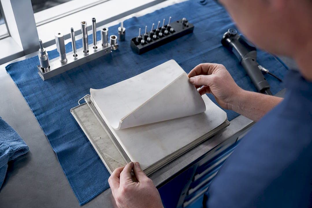
The most effective approach to any inspection is a structured, standards-backed workflow: plan the job, prep the surface, verify calibration, apply the right method for the defect type, interpret the result against the governing code, then document it with photos and metadata. Skip any one of those steps and you raise the odds of a missed defect, according to the standard NDT inspection process breakdown.
Here's the shortlist to start with on any job, veterinary or industrial:
- Visual testing (VT), direct or remote, as your first and fastest screening tool
- Thermography, passive for routine energized systems, active when you need to force thermal contrast
- Liquid penetrant (PT) or magnetic particle (MT) for surface-breaking cracks
- Ultrasonic (UT) or radiographic (RT) testing for internal, volumetric defects
One number worth remembering: industry guidance on NDT method selection notes that visual testing alone typically catches the majority of indications before any other method even gets set up. That's why VT sits at the front of every workflow below, not as an afterthought before the "real" testing starts.
Table of Contents
- Planning and pre-inspection checklist for technicians
- What Makes Visual Testing the Foundation of Every Inspection?
- When Should You Use Passive vs. Active Thermography?
- Which NDT Method Should You Use for Each Defect Type?
- Common Inspection Mistakes That Cost You Accuracy
- What Belongs in an Inspection Report?
- How Should You Maintain and Calibrate Inspection Equipment?
- Printable Field Cheat Sheets for On-Site Use
- Inspection Techniques for Vet and Industrial Techs: An Editorial Take
- Sources
Planning and pre-inspection checklist for technicians
A rushed setup is where most missed defects begin, not during the actual scan. Before you touch a scope or a probe, confirm these items in order:
- Scope and acceptance criteria — know which code applies (ASME, AWS, API, or a client-specific spec) before you start.
- Part identification and orientation — mark or photograph the component so nothing gets mixed up later.
- Access and safety plan — PPE, lockout/tagout, confined-space entry permits, and a second person on standby if required.
- Equipment readiness — calibration verified, batteries charged with spares, optics cleaned, couplants and consumables stocked.
- Environmental conditions logged — temperature, humidity, and (for thermography) solar loading, recorded before you start.
- Baseline photo taken of the component in its as-found condition.
Pro Tip: Run a quick functional calibration check immediately before any critical inspection, not just at the start of your shift. A UT probe that was fine at 7 a.m. can drift by noon, and a wrong reference block invalidates the entire session, per common calibration failure points.
If access is unsafe or prep is incomplete, delay the inspection. A rescheduled job costs less than a bad report.
What Makes Visual Testing the Foundation of Every Inspection?
Visual testing should be your first move on every job, full stop. It's the fastest way to catch surface issues, and it directs everything that follows: a suspicious weld toe or a hairline crack found by eye tells you exactly where to point your UT probe or PT dye next.
Direct visual testing (DVT) means you or your optics are looking straight at the surface, unobstructed. Remote visual testing (RVT) comes in when geometry or safety rules out direct access: inside a pipe, behind a shield, or in a body cavity where a rigid or flexible endoscope has to do the looking for you. According to ASNT's overview of the method, VT's biggest limitation is that it's line-of-sight and depends heavily on the inspector's experience and interpretation.
Field technique matters more than most technicians assume:
- Keep viewing distance within about two feet whenever practical, at an angle no shallower than 30 degrees.
- Match lighting to the job. Welding codes call for specific minimum foot-candle levels, and dim or uneven light hides exactly the flaws you're looking for.
- Use mirrors for tight angles, magnifiers (5x is a common field standard) for fine surface detail, and borescopes or video scopes for anything you can't reach directly.
- Shadow the surface deliberately. Raking light across a weld bead reveals undercut and porosity that flat lighting flattens out.
For photo documentation, frame every shot with a scale reference and a clear orientation mark, whether that's a compass note on a tank shell or a clock-position label on an endoscopic image. In veterinary work, that also means protecting the animal and the site from unnecessary handling; in industrial settings, it means staying clear of energized components while you shoot. A flexible borescope guide covers the handling side of this in more depth.
When Should You Use Passive vs. Active Thermography?
Use passive thermography on systems already running under normal load, like an energized electrical panel or a bearing in service. Switch to active thermography, where you apply an external heat source or forced cooling, when the component isn't generating enough thermal contrast on its own, such as checking a composite panel for subsurface delamination. Level I thermography training covers exactly this distinction, along with the basic rules for qualitative image capture, according to the thermal imaging curriculum/08%3A_Inspection_Techniques).
Camera setup matters as much as the scan itself:
- Set emissivity to match the target material as closely as you can estimate it. Shiny metal and painted surfaces behave very differently under an IR sensor.
- Keep distance and angle appropriate to your sensor's resolution. Too far away and small hotspots blur into the background.
- Decide upfront whether you need a qualitative scan (does anything look abnormal?) or a quantitative one (what's the actual temperature delta?). Quantitative work demands tighter emissivity control and steady-state conditions.
- Log wind, solar loading, and ambient temperature. A sunny building envelope scan taken at 2 p.m. can hide the same defect a 6 a.m. scan would show clearly, per the same environmental guidance.
| Situation | Better method |
|---|---|
| Electrical hotspots, breaker panels | Thermography (passive) |
| Bearing or motor heat patterns | Thermography (passive or active) |
| Building envelope, insulation gaps | Thermography (steady-state, controlled ambient) |
| Subsurface cracks, wall thinning | Ultrasonic testing (UT), not thermography |
| Surface-breaking cracks on welds | Penetrant or magnetic particle, not thermography |
Which NDT Method Should You Use for Each Defect Type?
The decision is simpler than it looks once you sort by defect location. Surface-breaking flaws call for liquid penetrant (PT) or magnetic particle (MT) testing. Internal or volumetric defects, like porosity buried in a weld or wall-thickness loss in a pipe, call for ultrasonic testing (UT) or radiography (RT). Thin conductive materials with hidden corrosion or cracking are a job for eddy current testing (ET).
- PT works on any non-porous material but only finds flaws open to the surface.
- MT is fast and cheap but limited to ferromagnetic materials only, so it's useless on aluminum or stainless.
- UT gives excellent sensitivity to planar defects and doubles as a thickness gauge, and it doesn't need access to both sides of the part, according to a comparison of RT and UT tradeoffs.
- RT produces a permanent image record, useful for archival and legal purposes, but needs access to both sides of the component plus radiation exclusion zones.
| Indication found by VT/thermography | Confirm with |
|---|---|
| Surface crack or linear indication | PT (non-ferrous) or MT (ferrous) |
| Suspected internal void or lack of fusion | UT or RT |
| Thin-wall corrosion under coating | ET |
When code requires it, or when a finding is borderline, hand it off to a Level II or III inspector rather than guessing. RT in particular carries safety and licensing constraints that go beyond a typical field technician's scope.
Common Inspection Mistakes That Cost You Accuracy
Most missed defects trace back to a handful of repeat offenders: skipping surface prep, trusting an uncalibrated instrument, using a guessed emissivity value, working under poor lighting, and mistaking a geometric artifact for an actual flaw. Oil film, rust, and old paint routinely mask surface-breaking cracks even from a well-trained eye, according to findings on surface contamination.
- Clean the surface to the standard your method requires, not just "clean enough to see."
- Verify calibration against a known reference block or standard before, not after, a critical scan.
- Look up emissivity values for the actual material rather than eyeballing a camera default.
- Match lighting levels to the code's minimum, and check twice on overcast days or in shadowed bays.
- Cross-check a suspicious indication against the governing code (ASME, AWS, API) before calling it a defect.
Pro Tip: When a finding sits right on the edge of acceptance criteria, get a second set of eyes on it. Fatigue and rushed inspections cause more borderline misses than bad equipment ever does.
What Belongs in an Inspection Report?
Report what you saw, how you tested it, what your equipment was calibrated against, and your recommended disposition, whether that's accept, monitor, or repair, tied directly to the acceptance criteria that governs the part.
A solid field report includes:
- Component ID and location
- Method used and key settings (emissivity, probe frequency, lighting level)
- Calibration reference and date
- Environmental conditions at time of test
- Annotated photos with scale, orientation, and both overview and close-up shots
- Time stamps and your action recommendation
To build one quickly on-site:
- Photograph the component before and during testing, including a scale marker in every shot.
- Record equipment settings and calibration reference numbers as you go, not from memory afterward.
- Note environmental conditions the moment you start, since they can shift mid-inspection.
- Write your disposition in plain language: accept, monitor with a re-inspection date, or flag for immediate repair.
- For urgent findings, call it in to maintenance or veterinary staff before you finish the paperwork. A written report that arrives after the shift ends helps nobody.
Good documentation matters as much as the detection itself, since clients and regulators often audit these records years later according to reporting best practices. An endoscopic imaging workflow guide walks through image capture and metadata habits in more detail if you want to tighten this up.
How Should You Maintain and Calibrate Inspection Equipment?
Regular cleaning, correct sterilization for anything used on animals, and current calibration records are not optional extras. They're the baseline that makes your results defensible.
- Clean and visually inspect scopes daily, before and after use.
- Run scheduled deep-clean or sterilization cycles on any endoscope used in animal procedures, following a documented protocol like the one in this sterilization guide.
- Store flexible scopes coiled loosely to avoid sharp bends that damage internal fiber bundles.
- Replace consumables (couplants, penetrant dye, cleaning wipes) on a set interval rather than waiting until they run out mid-job.
- Log every calibration check: date, reference standard used, and technician initials. Run a functional check before each shift, and send equipment out for full calibration on the manufacturer's schedule or sooner if results look off.
Safety rules scale with the method. RT demands radiation exclusion zones and dosimetry. Working near energized industrial equipment demands a documented safe approach distance. Chemical penetrants require gloves and ventilation. Confined-space work requires a permit and a standby observer, no exceptions.
Pro Tip: Keep a small calibration verification kit and a spare set of consumables in your field bag. A canceled job because a reference block got left in the shop costs more than the kit ever will.
Printable Field Cheat Sheets for On-Site Use
Save these as phone-ready notes or print them for a clipboard. A one-page checklist beats trying to remember six things at once in a confined space.
VT quick check: clean surface, adequate lighting, distance within 24 inches, angle over 30 degrees, photo with scale marker.
Thermography quick check: passive or active decision made, emissivity set, ambient conditions logged, steady-state confirmed if quantitative data is needed.
Escalation rule: surface indication → PT/MT. Suspected internal flaw → UT/RT. Thin-skin conductive concern → ET. Borderline call → Level II/III review.
Top five photo rules: scale marker in frame, orientation noted, overview plus close-up, consistent lighting, file named with date and component ID. Save checklists as PDF or a locked note file on your phone so they don't get accidentally edited mid-job, and always attach calibration and photo metadata to the final report.
| Inspection type | Top action to remember |
|---|---|
| Visual testing | Distance, angle, and lighting before you shoot |
| Thermography | Confirm emissivity and steady-state before quantitative claims |
| Surface-breaking suspicion | Escalate to PT or MT, not UT |
| Volumetric suspicion | Escalate to UT or RT, confirm access constraints |
| Any finding | Log calibration reference with the report |
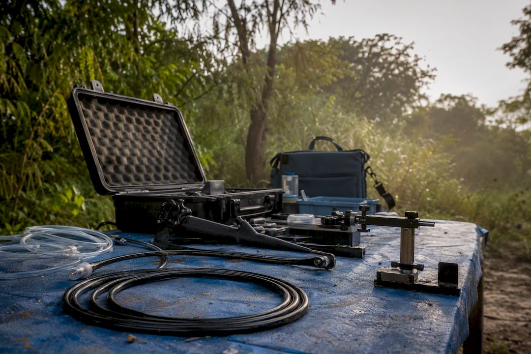
Field kits built around a portable video inspection system or a solid borescope selection make it easier to hit these checkpoints without hauling extra gear. For veterinary technicians specifically, pairing rigid scope options from the veterinary endoscopy catalog with a documented sterilization routine keeps both compliance and animal safety intact. Clinics like Animal Care of Hobe Sound rely on the same principle: visual judgment backed by consistent technique, not just better hardware.
Inspection Techniques for Vet and Industrial Techs: An Editorial Take
The conventional advice on inspection technique spends too much time on which tool to buy and not enough on the sequence you run it in. A $30,000 borescope in the hands of someone who skipped surface prep will miss the same crack a $300 flashlight would catch if the surface had been cleaned first. That's the uncomfortable truth buried in most training material: equipment quality is a multiplier, not a substitute, for discipline.
What's overrated is chasing the newest sensor resolution or the latest AI-assisted defect flagging. What's underrated is the boring stuff: calibration logs, consistent photo angles, and knowing your acceptance code well enough to catch a borderline call before it becomes a liability. Digital tools genuinely expand what a technician can see, but they still can't tell you whether an indication is a rejectable defect or a harmless artifact. That judgment call remains entirely yours.
If you take one thing from this guide, make it the checklist habit, not the gear list. Technicians who write things down consistently outperform technicians with better cameras and worse notes.