
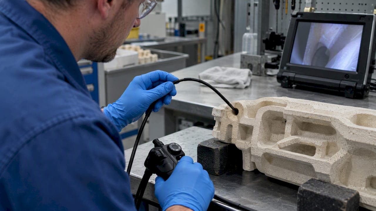
A borescope is the right first-line tool for surface screening and geometry checks of ceramic cores, but it does not replace microfocus X-ray or CT for volume defects. It catches surface-connected porosity, cracks, core wash, and dimensional problems quickly and cheaply. It cannot reliably resolve most subsurface flaws below roughly 50 to 500 micrometers, so when a part is critical or an indication looks suspect, escalate to a volume-sensitive method, and document everything along the way.
TL;DR:
- Match probe diameter to the narrowest passage, typically 2.4 to 6 mm, and use an articulated flexible scope for bends or shifting geometry.
- Start with diffuse light for passage mapping, switch to angled light for cracks, and save timestamped video with part IDs and calibration details.
- Apply ASTM A997 criteria to surface findings; reject clear cracks above limits, but escalate ambiguous indications or high consequence parts to volume inspection.
- Standard borescopes miss subsurface flaws; microfocus radiography and CT resolve 20 to 50 micrometer features under controlled conditions, so reserve them for suspect or critical parts.
Table of Contents
- Borescope capabilities relevant to ceramic cores
- Step-by-step inspection workflow for ceramic cores using a borescope
- Selecting borescope probe specs and accessories for ceramic core inspection
- Interpreting visual findings: defects typical in ceramic cores and relevant standards
- When to use complementary NDT methods and how borescope fits into a multi-method inspection program
- Maintenance, calibration, and reporting best practices for borescope inspections
- Research-backed material notes and documented detection limits
- A supplier's view on field constraints in ceramic core inspection
- Equipping your inspection program with the right borescope
- FAQ
- Sources
Borescope capabilities relevant to ceramic cores
Choosing the right borescope for ceramic core work starts with matching the probe to the passage, not the other way around. Core passages in investment castings and other ceramic components often run narrow and twist through complex internal geometry, so probe diameter and access clearance drive every other decision.
Flexible videoscopes used for core inspection typically run from about 2.4 mm to 6 mm in outer diameter, small enough to pass through gating channels and feed passages without forcing the part open. Articulation matters just as much as diameter. A probe with two-way or four-way tip articulation, usually rated in the 90 to 180 degree range, lets a technician steer around core shifts and bends instead of guessing at an indication from a fixed angle.
Optics set the ceiling on what you can actually see. Standard borescope optics resolve surface topology and color contrast well, which is exactly what you need for porosity clusters, core wash staining, and surface cracking, but they are not a substitute for dimensional metrology on features smaller than the optical resolution of the lens and sensor.
Illumination strategy often matters more than raw resolution. Diffuse lighting flattens shadows and helps with general surface mapping, while angled or raking light grazes across a surface and throws fine cracks or porosity edges into relief that direct lighting would wash out. Some inspectors add polarizing filters to cut glare off glazed or wet ceramic surfaces.
Recording and measurement overlays close the loop on traceability. A system that timestamps video, tags part IDs, and overlays calibrated measurement grids turns a visual pass into a defensible inspection record rather than an anecdote.
Key hardware factors to weigh before an inspection:
- Probe diameter: match to the smallest passage you need to traverse, typically 2.4 to 6 mm for core work.
- Articulation: two-way or four-way steering in the 90 to 180 degree range improves reach into bends.
- Optics and sensor resolution: determines the smallest surface feature you can confidently characterize.
- Illumination mode: diffuse for general mapping, angled or raking light for fine crack and porosity detection.
- Recording and overlays: timestamped video with measurement overlays supports traceable reporting.
Published research on ceramic NDE notes that scanning acoustic microscopy and microfocus radiography can resolve features down to about 20 to 50 micrometers under controlled conditions, a resolution range well beyond what standard visual borescoping achieves on its own.
Step-by-step inspection workflow for ceramic cores using a borescope
A repeatable workflow is what separates a defensible inspection record from a quick look with a camera. The sequence below reflects how technicians typically move from setup to a documented disposition decision.
- Prepare the part and the tool. Clean the core passage of loose debris, dust, and residual binder material; fixture the part so it will not shift during probe insertion; verify the borescope's calibration status and battery or power supply before starting.
- Plan access. Identify entry ports that give the straightest line to the area of interest, and use protective sleeves or guide tubes on fragile core edges so the probe tip never bears directly on a brittle feature.
- Route the probe. Advance slowly, pausing at junctions and bends rather than forcing the tip; a core shift or unexpected step in geometry is often the first sign of a defect worth a second look.
- Set imaging parameters. Select diffuse lighting for an initial survey pass, then switch to angled lighting when a suspect area needs more contrast; frame each feature of interest square to the lens rather than at a raking angle to avoid size distortion.
- Capture and annotate. Record video continuously rather than relying on still frames alone, and apply measurement overlays to any feature you intend to report with a size estimate.
- Document. Use a consistent filename convention that encodes part ID, inspection date, and operator initials; timestamp every clip; log probe serial number and calibration date alongside the part record.
- Apply decision gates. Compare findings against the applicable acceptance standard; if an indication exceeds the visual threshold or its nature is ambiguous, flag it for escalation rather than making a judgment call from video alone.
- Dispose. Accept, reject, or escalate to volume-sensitive NDT based on the documented findings, and route the record into the quality file.
The decision gate in step 7 is where most inspection programs either save money or waste it. A borescope pass that clearly shows a surface crack exceeding the acceptance limit in ASTM A997 can justify an immediate reject without further testing. An ambiguous shadow or a feature that might be subsurface porosity is a different story, and that is exactly the case where escalation protects both the part and the inspection program's credibility.
Our industrial borescope field guide walks through additional configuration notes for routing probes through tight passages in production settings.
Pro Tip: Pause at every visible junction in the core passage rather than pushing through; most missed indications happen when a technician advances the probe too fast through a bend and never frames the far wall.
Selecting borescope probe specs and accessories for ceramic core inspection
The choice between a flexible videoscope and a rigid or semirigid probe comes down to channel geometry. Straight or gently curved passages tolerate a rigid probe, which generally delivers sharper optics and simpler handling. Core passages with bends, branches, or unpredictable shifts need a flexible videoscope with active articulation, even though flexible optics trade a bit of sharpness for reach.
Diameter selection follows the same logic as any access-limited inspection: go as large as the passage allows, because larger probes carry bigger sensors and brighter illumination, but never so large that the tip risks contacting and damaging a fragile core wall. Most ceramic core work settles in the 2.4 to 6 mm range, with narrower feed passages sometimes requiring micro-fiber probes below that.
Macro-focus capability and measurement overlays are not optional extras once you intend to size a defect rather than just note its presence. A probe that can rack focus down to a few millimeters from the tip, paired with an overlay calibrated against a known artifact, turns "there's a crack" into a measured feature with a defensible uncertainty band.
A practical accessory checklist for ceramic core work:
- Non-scratching tip guards to protect both the probe and brittle ceramic surfaces during insertion.
- Clean, undamaged sheaths, replaced or inspected regularly to avoid dragging embedded grit across a core wall.
- Anti-reflection diffusers for glazed or wet surfaces where glare obscures fine cracking.
- Calibration artifacts (gauge blocks or certified targets) to verify measurement overlay accuracy before each shift.
Portability, battery life, and wireless image capture matter most in field or production-floor settings where a technician moves between stations all day. Our dual-camera borescope guide covers how a second onboard camera can support simultaneous wide-angle and close-up framing, which is useful when documenting both the overall passage and a specific indication in the same pass.
Interpreting visual findings: defects typical in ceramic cores and relevant standards
Ceramic cores fail in a handful of recognizable ways, and each one has a distinct visual signature under borescope lighting.
- Porosity and blowholes appear as rounded voids or clusters, often with a slightly darker shadow line at the edge under angled light.
- Core wash buildup or flaking shows up as a textured or discolored patch, sometimes with visible separation from the underlying core material.
- Cracks read as thin, often branching lines that gain contrast dramatically under raking illumination compared to diffuse lighting.
- Core shift presents as a visible step or misalignment in wall thickness as the probe traverses the passage, rather than a discrete flaw at one point.
Visual screening has a practical floor. Conventional visual and liquid penetrant methods reliably catch surface-connected flaws, but research on ceramic NDE notes that detecting flaws down into the 20 to 50 micrometer range generally requires specialized high-resolution methods, not standard optical inspection. Any size estimate from borescope video should be reported with that uncertainty acknowledged rather than stated as a precise measurement.
ASTM A997 gives the surface acceptance framework most investment casting programs use to judge visual findings, with defined criteria across inspection levels and an expectation that components are free of linear discontinuities per the standard's thresholds. For tubular ceramic or core passages inspected by probe, ASTM A1015 guides how illumination, probe speed, and focus should be customized to the application rather than run on fixed default settings.
Reporting language should separate what was seen from what it means: "observation" for a raw visual note, "measured feature" for anything carrying an overlay-derived dimension and its uncertainty, and "recommended follow-up" for any indication that falls outside the acceptance criteria or remains ambiguous after the visual pass. Our casting defect borescope guide works through several of these defect signatures in more detail.
When to use complementary NDT methods and how borescope fits into a multi-method inspection program
A borescope answers "is there a surface problem here" quickly and cheaply. It does not answer "is there a void buried inside this wall," and treating it as if it does is the most common mistake in ceramic core inspection programs.

Literature on ceramic NDE places many volume-flaw detection thresholds in the 20 to 500 micrometer range, well below what standard optical borescoping resolves, which is why microfocus radiography and CT exist as a dedicated escalation tier rather than a routine first step. The trigger for escalation is usually one of three things: the component is flight-critical or otherwise high-consequence, the borescope pass turned up an ambiguous or suspicious indication, or a production sample has already failed and root-cause analysis is underway.
A practical multi-method workflow looks like this:
- Screen every part with borescope visual inspection against ASTM A997 acceptance criteria.
- Escalate suspect parts to microfocus X-ray, CT, or scanning acoustic microscopy when indications exceed visual thresholds or remain ambiguous.
- Reserve full CT runs for critical components or periodic sample audits rather than every unit, since CT time and cost scale with resolution demands.
- Route confirmed defects into failure analysis and root-cause testing to catch systemic process issues.
A Springer review of ceramic inspection methods confirms this tiered approach is common practice: borescopes handle rapid production screening, while CT and microfocus radiography are reserved for suspect parts and periodic audits to control cost.
Maintenance, calibration, and reporting best practices for borescope inspections
An inspection record is only as good as the equipment and documentation behind it. A few procedural habits keep both audit-ready.
- Check calibration daily before the first inspection and log the check against a certified target.
- Tie every image to a record: part ID, probe serial number, operator ID, and the calibration record date it was captured under.
- Clean sheaths and tips between inspections to avoid dragging embedded particles across a ceramic surface, which can scratch both the part and the probe.
- Retire probes proactively once optical quality degrades or a tip shows damage, and document the reason rather than quietly swapping equipment.
Our prepping endoscope best practices guide covers the daily check sequence in more detail for teams building out a formal procedure.
Pro Tip: Log calibration checks the same way you log inspection findings, with a timestamp and operator initials; an undocumented calibration is functionally the same as no calibration when a report gets audited.
Research-backed material notes and documented detection limits
Ceramic materials present inspection challenges that differ from metals, largely because flaw populations skew smaller and the materials themselves can mask subsurface features from optical and even some acoustic methods. Published NDE research on ceramics and ceramic composites describes a layered approach: visual and liquid penetrant methods for surface-connected flaws, and microfocus radiography, CT, or scanning acoustic microscopy for the volume flaws that visual methods miss entirely.
- Visual borescoping reliably screens surface-connected porosity, cracking, and core wash.
- Microfocus radiography and CT extend detection into the 20 to 50 micrometer range under controlled conditions.
- A Springer Nature review of ceramic inspection methods confirms that newer optical, thermal, and acoustic techniques are still under active development for this material class.
- ASTM A1015 formalizes how videoborescoping parameters should be customized per application rather than standardized blindly.
Conventional visual and liquid penetrant inspections screen surface-connected flaws effectively, while specialized high-resolution methods are required to reliably detect flaws down to 20 to 50 micrometers.
That gap between what a borescope shows and what a critical ceramic component actually needs is the reason a sound inspection program treats visual screening as the first filter, never the final word.
A supplier's view on field constraints in ceramic core inspection
Technicians most often tell us about three constraints: passages too tight for a standard probe, cores too fragile for careless handling, and a need for measurement overlays that hold up under audit. We configure probe diameter, tip guards, and sheathing around the specific passage geometry a customer describes, and we can build custom probe and calibration configurations on request rather than leaving a team to force a generic setup into an awkward access point.
— Endoscope
Equipping your inspection program with the right borescope
There are small-diameter videoscopes, portable SD-card recorders, and micro fiber borescopes suited for the access constraints ceramic core work demands, along with non-scratch tips and sheaths that protect brittle surfaces during routing. Support teams often configure custom probe and calibration setups rather than relying on generic kits.
- Borescopes and videoscopes: small-diameter, monitor-type SD-card systems for core passage access.
- Repairs and custom configuration: direct support for probe damage, sheathing, and calibration needs.
- Accessories: biopsy forceps, measurement-overlay-capable systems, and protective tips for fragile ceramic surfaces.
| Need | Where to look |
|---|---|
| Browse borescope and videoscope product classes | Borescopes category page |
| Request repairs or custom probe configuration | Repairs and equipment landing page |
| Source accessories like biopsy forceps | Biopsy forceps page |
Browse our borescope and videoscope lineup to find a configuration that matches your core passage geometry, or reach out through our support and repairs page for a custom probe or calibration setup.
FAQ
What size borescope do I need for ceramic core inspection?
Most ceramic core passages call for a probe between 2.4 mm and 6 mm in outer diameter, with narrower feed passages sometimes requiring micro-fiber probes below that range. Choose the largest diameter the passage safely tolerates, since larger probes carry better sensors and illumination.
Can a borescope detect subsurface cracks in ceramic cores?
A borescope reliably shows surface-connected cracks and porosity but cannot resolve most subsurface or volume flaws, which research on ceramic NDE places in the 20 to 500 micrometer detection range depending on method. Suspect subsurface indications should be escalated to microfocus radiography, CT, or scanning acoustic microscopy.
Which ASTM standard governs visual acceptance for ceramic core castings?
ASTM A997 provides the surface acceptance criteria most investment casting programs use to judge visual borescope findings, including linear discontinuity thresholds across inspection levels. ASTM A1015 separately guides how videoborescoping parameters should be customized for tubular and passage-style inspections.
Does 1800endoscope offer custom borescope configurations for ceramic inspection?
We configure probe diameter, sheathing, and calibration setups around specific passage geometries on request rather than relying on a single generic kit. Reach out through our equipment and repairs page to discuss a configuration for your application.
When should I escalate from borescope screening to CT or microfocus X-ray?
Escalate when the component is high-consequence, when a borescope pass turns up an ambiguous or suspicious indication, or after a production sample has already failed and root-cause analysis is underway. This tiered approach, screening everything visually and reserving CT or microfocus radiography for suspect parts, is standard practice described in published reviews of ceramic inspection methods.
Sources
- A997/A997M Standard Practice for Investment Castings, Surface Acceptance Standards, Visual Examination
- A1015 Standard Guide for Videoborescoping of Tubular Products for Sanitary Applications
- NDE of ceramics and ceramic composites (research library excerpt)
- Inspection of Ceramic Materials | Springer Nature