
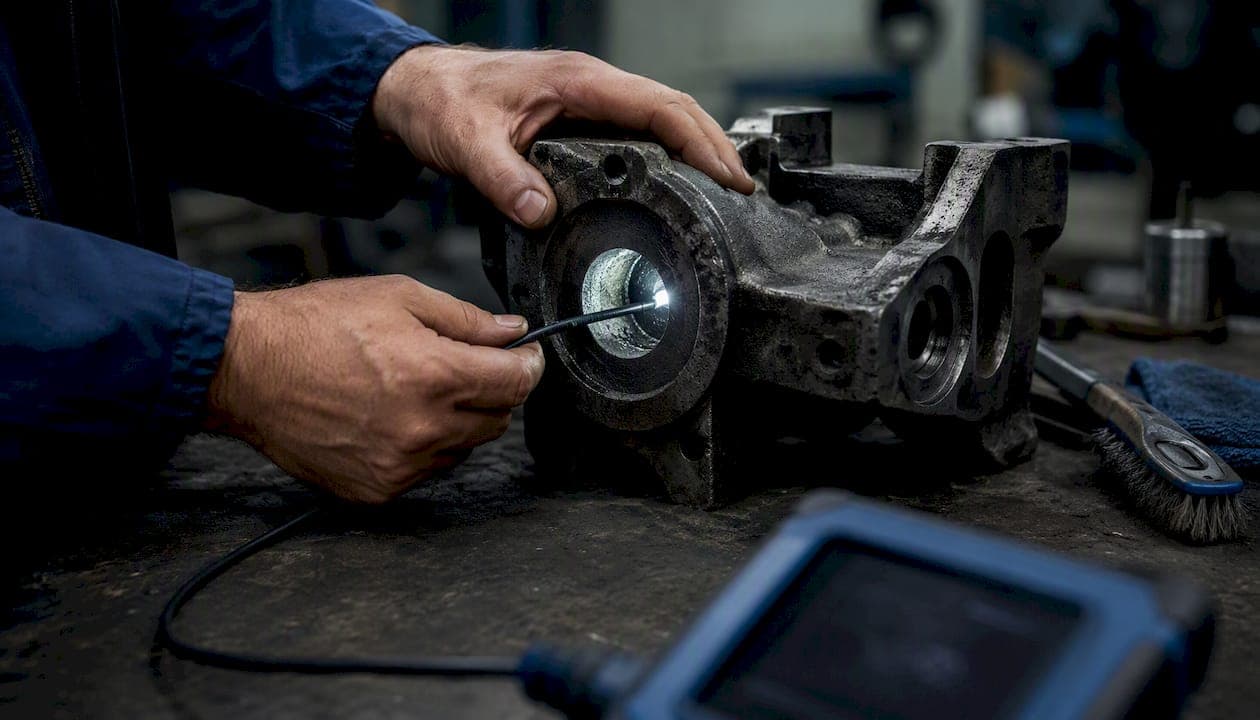
A properly specified micro or video borescope reliably finds porosity, internal cracks, inclusions, cold shuts, sand residue, and incomplete drill-throughs in metal castings — provided you match probe diameter, articulation range, lighting, and image resolution to the part geometry. The four specs that most directly determine detection capability are probe outer diameter (which sets your minimum access bore), working length (which determines how deep you can reach), articulation range (which controls whether you can angle the camera around corners), and camera resolution combined with LED brightness (which decides whether fine porosity or hairline cracks are visible at all).
One operational caveat: borescopes are a line-of-sight tool. Highly polished internal surfaces create specular glare that can mask fine defects, and a single insertion covers only a fraction of a complex casting's internal geometry. Plan your sampling rate before you start.
- Confirm the smallest entry bore diameter on your part and select a probe at least 0.5mm smaller.
- Match working length to the deepest feature you need to reach.
- Specify 4-way articulation for any passage with bends or cross-holes.
- If a defect is suspected but not confirmed visually, escalate to dye-penetrant testing (PT) or X-ray computed tomography (CT).
Pro Tip: Use a rigid micro borescope when the bore is straight and short — rigid scopes deliver sharper optics at lower cost. Switch to a flexible videoscope the moment the passage bends more than 15–20 degrees or exceeds roughly 300mm in depth.
Key Takeaways
A borescope matched to the part geometry reliably detects porosity, cracks, inclusions, cold shuts, and burrs in metal castings — but only when the inspection plan covers the right passages at the right sampling rate.
| Point | Details |
|---|---|
| Match probe to bore geometry | Probe outer diameter must be at least 0.5mm smaller than the entry bore; specify 4-way articulation for any bent passage. |
| Prioritize lighting control | Adjustable LED brightness matters as much as camera resolution on polished or reflective internal surfaces. |
| Plan coverage systematically | A systematic insertion sequence with a side-viewing adaptor finds more defects than a single straight-through pass with a higher-resolution camera. |
| Document every finding | Record still images, video, insertion depth, and location map for every inspection — not just for rejects. |
| Escalate when borescope reaches its limit | If a passage cannot be navigated or imaged clearly, log it as "could not inspect" and escalate to PT, UT, or X-ray CT. |
| 1800endoscope for probe selection | 1800endoscope stocks HD videoscopes, small-diameter probes, and accessories suited to casting inspection across a range of bore sizes. |
Table of Contents
- Why borescope inspection is essential in casting quality control
- Common casting and machining defects you can find with a borescope
- Practical challenges when inspecting internal features
- Borescope types and the key specs that determine what defects you can detect
- Step-by-step borescope inspection workflow for cast components
- How to interpret borescope images and avoid common false positives
- Best practices for documenting borescope inspections
- Cleaning, maintenance, and operator safety for borescope use in foundries
- When and how to augment borescope inspection with video-sequence AOI or robot-assisted inspection
- Quick checklist for specifying or buying a borescope for casting inspection
- A practitioner's perspective on what actually works in the field
- 1800endoscope carries the probes and accessories your casting inspection needs
- Sources
Why borescope inspection is essential in casting quality control
Remote visual inspection (RVI) with borescopes sits at the front of the non-destructive testing toolkit precisely because it is fast, non-destructive, and gives a real-time image from inside a part that would otherwise require sectioning to see. Catching a porosity cluster or a sand inclusion before a component reaches final machining or assembly avoids the compounding cost of rework at a later stage — and in safety-critical applications like hydraulic manifolds or turbine housings, it avoids field failure entirely.
The business case is straightforward. Destructive inspection — cutting or sectioning a casting to examine its interior — consumes the part and is statistically limited to a tiny sample. Borescope inspection is repeatable on every unit if throughput allows, and it generates a visual record that supports supplier disputes, process audits, and corrective action reports. First-pass yield improves when defects are caught at the casting stage rather than after expensive CNC machining has been applied to a flawed blank.
Parts and industries where borescope inspection delivers especially high value:
- Engine blocks and cylinder heads: oil galleries, coolant passages, and combustion chamber ports are prone to sand residue and porosity.
- Hydraulic manifolds: blind cross-bores and intersecting passages trap burrs and machining debris that cause valve seat failure.
- Turbine and compressor housings: internal cooling channels in investment castings are inspected for wall-thickness variation and crack initiation.
- Valve bodies and pump housings: internal flow paths require verification of bore geometry and freedom from inclusions.
- Precision die castings: thin-wall sections are susceptible to cold shuts and misruns that are invisible from the exterior.
Inspection cameras used in these applications generate documentation that feeds directly into statistical process control (SPC) and supplier quality programs.
Common casting and machining defects you can find with a borescope
Casting defects cover a wide range of discontinuities, and a borescope reaches many of them when the geometry allows access. Here is a working taxonomy with visual cues and process implications:
- Porosity and gas voids: Appear as rounded pits or clusters of small holes on the internal surface, often with a matte finish. Caused by dissolved gas or shrinkage during solidification. Clusters near a gate or riser indicate a process parameter issue.
- Shrinkage cavities: Larger, irregular voids with a rough, jagged interior surface. Typically found in thick sections where the metal solidifies last. Distinguish from gas porosity by the irregular, branching shape.
- Internal cracks: Appear as sharp, linear discontinuities with defined edges, often following grain boundaries or stress concentration points. Unlike a scratch from tooling, casting cracks rarely have a bright, machined appearance.
- Cold shuts: A visible seam or fold line where two metal flows met but did not fully fuse. The seam is typically smooth-edged and runs across the surface rather than into it.
- Misruns: Areas where the metal did not fill the mold completely, leaving a rounded, incomplete edge or a thin, translucent-looking wall section.
- Inclusions and foreign material: Sand, slag, or oxide particles embedded in the surface appear as dark spots or irregular patches with a different texture or color than the surrounding metal.
- Sand residue: Loose or bonded sand remaining in a passage after shakeout. Visible as granular deposits, often tan or gray, that may shift when the probe moves.
- Incomplete drill-throughs and blind holes: A bore that should break through to another passage but terminates in solid metal. Visible as a flat or rounded end wall where an opening is expected.
- Burrs at cross-holes: Thin metal fins projecting into the bore at the intersection of two drilled passages. They appear as bright, sharp projections under LED illumination.
- Flow lines: Parallel surface striations from metal flow during casting. These are a normal surface texture in many processes, not a structural defect.
Pro Tip: The most common false call in casting inspection is mistaking normal die-casting surface texture — the fine, regular pattern left by the mold surface — for porosity. True porosity breaks the pattern: the pits are irregular in size and spacing, and they often have a slightly different reflectivity than the surrounding surface. If the pattern is perfectly regular and repeats across the whole surface, you are looking at mold texture, not a defect.
Practical challenges when inspecting internal features
Access is the first constraint, and it shapes every other decision. Many castings have entry holes sized for function, not inspection — a 4mm oil gallery or a 3mm cross-bore leaves almost no margin for probe diameter. Tortuous passages with multiple bends can stop a semi-rigid probe entirely, and blind pockets with no exit hole limit how much of the cavity wall you can see from a single insertion point.
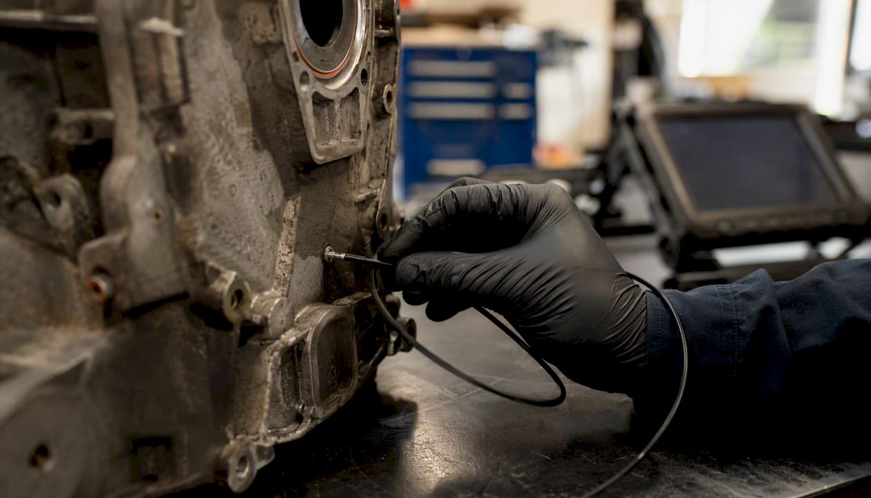
Optical challenges compound the access problem. Highly polished or freshly machined bores reflect LED light directly back into the lens, creating bright glare spots that obscure the surface beneath. Rough sand-cast surfaces scatter light more evenly, which is actually easier to image, but the irregular texture makes it harder to distinguish a true void from a shadow. Field of view (FOV) and depth of field (DOF) trade off against each other: a wide-angle lens covers more surface per frame but reduces the apparent size of small defects, while a narrow FOV gives better defect resolution but requires more systematic coverage passes.
Environmental factors matter in foundry settings. Metal dust and coolant mist contaminate lenses quickly. Castings inspected shortly after shakeout may still be warm enough to fog optics or damage probe tips not rated for elevated temperatures. Operators working near induction furnaces or grinding stations face additional hazards that require PPE beyond what a standard inspection environment demands.
Sampling is a statistical problem that inspectors often underestimate. A single borescope insertion covers a narrow cone of view. For a complex hydraulic manifold with a dozen intersecting passages, full coverage requires a planned insertion sequence — and even then, some surfaces remain geometrically inaccessible. Defining which passages are inspected, at what sampling frequency, and what constitutes a representative sample for the lot is part of the inspection plan, not an afterthought.
Borescope types and the key specs that determine what defects you can detect
Three hardware categories cover most casting inspection scenarios.
Rigid borescopes use a relay lens system to transmit an image from tip to eyepiece or camera. They deliver the sharpest optics for a given diameter and are the right choice for straight, short bores. The trade-off is zero flexibility — any bend in the passage stops them cold.
Flexible fiber-optic borescopes route light and image through fiber bundles, allowing navigation through curved passages. Resolution is lower than rigid scopes of the same diameter because the fiber bundle limits pixel density, and the image has a characteristic honeycomb pattern at high magnification. They work well for longer, curved passages where image quality requirements are moderate.
Video borescopes (videoscopes) place a miniature camera chip at the probe tip, eliminating the fiber bundle entirely. This gives them the best image quality among flexible options, with true digital resolution, adjustable LED brightness, and the ability to record HD video and still images directly to storage. For casting defect inspection where documentation and image quality both matter, videoscopes are the standard choice in most professional QC environments. The 1800endoscope borescope catalog covers all three types, with videoscopes and small-diameter probes highlighted for industrial NDT work.
Spec checklist
Accessories that materially extend capability:
- Side-viewing adaptors: redirect the FOV 90 degrees, making cross-holes and lateral pockets visible from a straight insertion.
- Tip mirrors: similar function to side-viewing adaptors, useful on rigid scopes.
- Measurement overlays: software or reticle-based scales that let you estimate defect size on-screen without removing the probe.
- Extension tubes: add working length to a rigid scope for deeper straight bores.
Pro Tip: For small-diameter flexible probes, vendors rightly emphasize lighting control as much as pixel count. A 1080p camera with a fixed, non-adjustable LED is often outperformed by a 720p camera with variable brightness on reflective internal surfaces — the ability to dial down the LED is what separates a usable image from a washed-out one.
Step-by-step borescope inspection workflow for cast components
Pre-inspection planning
- Review the part drawing and identify every internal passage to be inspected, its nominal diameter, depth, and any bends.
- Define the sampling plan: 100% inspection, AQL-based sampling, or first-article only.
- Confirm the probe diameter, working length, and articulation type match the part geometry.
- Clean the entry holes of coolant, chips, and debris using compressed air or a lint-free swab.
- Verify the borescope display, recording function, and battery or power supply before starting.
Insertion and navigation
- Apply a thin film of compatible probe lubricant (silicone-based, not petroleum-based) to the probe tip and first 50mm of the insertion tube.
- Insert the probe slowly, with zero axial force beyond the probe's own weight where possible — forcing a flexible probe causes kinking.
- Use the articulation control to steer around bends; never rotate the entire probe body to change direction in a curved passage.
- Advance in short increments (20–30mm at a time) and pause to scan each section before moving deeper.
Imaging protocol
- Set LED brightness to the lowest level that gives a clear image — this reduces glare on polished surfaces.
- Adjust focus or zoom (if available) to fill the frame with the area of interest.
- Capture a reference still image at the entry point for location mapping.
- Record continuous video during navigation; supplement with still images at any area of interest.
- For each suspect area, capture at least two still images from slightly different angles to confirm the finding is not a lighting artifact.
Defect capture and location mapping
- Note the insertion depth (in mm from the entry face) and articulation direction for every finding.
- Sketch or annotate a part diagram with finding locations — this is the location map that goes into the inspection record.
- Use on-screen measurement overlays to estimate defect size when available.
Verification and escalation
- If a finding is ambiguous, use a side-viewing adaptor or reposition the probe to view from a different angle before calling it a defect.
- Confirm suspected cracks with a second pass at higher magnification or a different lighting angle.
- Escalate to dye-penetrant testing (PT) for surface-connected cracks, or to X-ray CT for volumetric defects that cannot be fully characterized visually.
How to interpret borescope images and avoid common false positives
Image artifacts are the main source of false calls in borescope inspection. Glare appears as a bright, featureless white area that expands when the probe is too close to the surface — back the probe out 5–10mm and reduce LED brightness before concluding the surface is defect-free. Motion blur from probe movement during video capture can make a smooth surface look cracked; always pause before capturing a still image. Lens contamination from coolant or metal dust creates dark spots or smears that do not move with the probe — clean the lens with a lint-free swab and isopropyl alcohol before re-inspecting.
For defect severity decisions, four checks help:
- Size threshold: Is the indication larger than the minimum rejectable size in your acceptance criteria (typically per ASTM or customer-specific drawing callouts)?
- Continuity: Does the indication have defined, continuous edges (crack, cold shut) or irregular, isolated boundaries (porosity, inclusion)?
- Contrast: Is the indication clearly darker or lighter than the surrounding surface, or does it blend in when lighting changes?
- Geometry: Does the shape match a known defect type, or is it consistent with a machining mark, mold parting line, or normal surface texture?
When an observation passes two or more of these checks, treat it as a probable defect and document it for disposition. When it passes none, log it as a surface anomaly and note that further NDT was not triggered.
Pro Tip: Use a measurement overlay or a calibrated reference target (a small disk of known diameter placed at the entry bore) to establish a pixel-to-millimeter scale before the inspection. Without a scale reference, estimating whether a void is 0.5mm or 2mm from a borescope image alone is unreliable — and that size difference often determines pass or reject.
Best practices for documenting borescope inspections
Every inspection record should contain, at minimum:
- Still images of each finding, labeled with part serial number, entry point, and insertion depth.
- Video clip of the full navigation sequence, stored with the part record.
- Location map: a part diagram or coordinate table showing where each finding was observed.
- Inspector ID and date/time of inspection.
- Equipment record: probe model, serial number, and last calibration date.
- Acceptance criteria invoked: the drawing revision, customer specification, or internal standard used to make the pass/hold/reject decision.
- Disposition: pass, hold for further review, or reject, with a brief rationale.
File naming convention: use a structure like [PartNumber]_[SerialNumber]_[Date]_[InspectorID]_[Sequence] so records sort chronologically by part and can be retrieved in seconds during an audit. Store images and video in a folder structure that mirrors your part numbering system, not by date alone.
For severity rating, a simple three-tier system works in most foundry QC environments: Pass (no rejectable indications found), Hold (indication present, disposition pending further NDT or engineering review), and Reject (indication exceeds acceptance criteria, part removed from flow). Note the specific criterion exceeded on every reject record.
Retention periods vary by industry and customer contract, but a minimum of three years is common for non-safety parts; safety-critical aerospace and automotive components typically require ten years or longer. Check your customer's quality agreement before setting retention policy.
Cleaning, maintenance, and operator safety for borescope use in foundries
Daily cleaning after each inspection session keeps optics clear and extends probe life significantly. Clean the lens tip with a cotton swab and IPA — never use acetone or ketone-based solvents on polymer-jacketed probes, as they attack the jacket material. Blow out the articulation section with low-pressure compressed air (under 30 PSI) to clear metal dust from the bending joints.
Periodic maintenance (monthly or per manufacturer schedule):
- Inspect the probe jacket for kinks, cuts, or abrasion damage. A kinked probe loses articulation control and can fail inside a bore.
- Check the articulation cables for slack or binding — uneven resistance in the control knob is an early warning sign.
- Verify the LED output has not dimmed; compare against a reference image taken at a known distance and brightness setting.
- Send the probe for factory service if the image shows fixed dark spots (dead pixels or contamination inside the optical path) that cleaning does not resolve.
Operator safety in foundry environments:
- Wear heat-resistant gloves when handling castings that have not fully cooled. A casting at 80°C feels manageable for a few seconds but causes burns on sustained contact.
- Use safety glasses rated for metal particle impact — grinding and shakeout operations nearby generate projectile debris.
- Never insert a borescope probe into a cavity that may contain pressurized gas or fluid without first confirming the part is depressurized and drained.
- Keep probe cables clear of moving machinery and hot surfaces during inspection.
Calibration and pre-inspection verification: Before any critical inspection, confirm the borescope is performing within spec by imaging a reference target (a calibration artifact with known feature sizes) and comparing the result to the baseline image on file. Log the verification check in the equipment record.
When and how to augment borescope inspection with video-sequence AOI or robot-assisted inspection
Static single-frame borescope inspection has a ceiling. For complex geometries or high-volume production where human fatigue and viewing-angle limitations affect consistency, multi-frame video strategies and robot-assisted trajectories offer a measurable improvement. A 2026 Scientific Reports study comparing automated optical inspection (AOI) setups found that optimized robot-assisted multi-angle video inspection increased correctly detected defective parts by a significant margin compared to single static images — a meaningful gain for safety-critical components where a missed defect carries high consequence.
The operational trade-offs are real. Robot-assisted inspection requires a fixturing system, a trajectory programming step for each new part geometry, and a curated annotated image dataset to train or validate the detection model. Integration complexity is higher than a handheld borescope, and throughput profiles change: cycle time per part may increase during setup but decrease at volume once the trajectory is optimized.
Practical rollout steps for teams considering this approach:
- Start with a fixed-camera pilot on a single high-volume part, collecting video across multiple production lots.
- Annotate defect frames with location and type, building a dataset before committing to a model.
- Evaluate detection performance using part-level aggregation rules (flag a part as defective if N or more matched detections appear across frames) rather than frame-level accuracy alone.
- Transition to a collaborative robot (cobot) arm for parts with complex geometry once the fixed-camera pilot validates the approach.
Scenarios where AOI or robot assistance is worth the investment:
- High-volume production of complex castings where manual inspection throughput is the bottleneck.
- Safety-critical parts (aerospace, automotive braking, hydraulic flight controls) where missed defects carry regulatory or liability consequences.
- Parts with internal geometries that require more than four probe insertions per unit to achieve adequate coverage.
- Processes with documented high false-positive rates from manual inspection, driving unnecessary rework costs.
Quick checklist for specifying or buying a borescope for casting inspection
Before writing a purchase request, confirm these parameters against your actual parts:
| Specification | Minimum Requirement | Notes |
|---|---|---|
| Probe outer diameter | At least 0.5mm smaller than smallest entry bore | Measure the bore — do not rely on nominal drawing dimension |
| Working length | Exceeds deepest feature depth by at least 100mm | Extra length gives handling margin |
| Articulation | 4-way for any passage with bends; 2-way acceptable for straight bores | 4-way adds cost; specify only where needed |
| Camera resolution | 720p minimum; 1080p for fine defect detection | Higher resolution increases file storage requirements |
| Lighting | Adjustable LED brightness | Fixed-brightness LED is a significant limitation on polished surfaces |
| IP rating | IP rating suitable for foundry and wet environments | Check the probe tip rating separately from the handle |
| Temperature rating | Probe tip rated for elevated temperatures appropriate for hot-casting inspection | Verify with the vendor for your specific operating temperature |
Operational requirements to confirm before purchase:
- Expected bore size range across all parts in scope (sets the probe diameter family you need).
- Maximum depth of the deepest feature (sets working length).
- Required inspection throughput (parts per hour) — this affects whether a single probe or multiple units are needed.
- Warranty terms and whether the vendor offers calibration services, spare probes, and tip adaptor kits.
Accessories to request with the initial order: side-viewing adaptor, measurement overlay software or reticle, spare probe tip (if field-replaceable), and a carrying case rated for the environment.
Sample procurement language for RFQs: "Supplier to provide a video borescope with probe outer diameter not exceeding [X]mm, working length not less than [Y]mm, 4-way articulation, minimum 1080p camera resolution, adjustable LED illumination, IP[Z] rating at the probe tip, and probe tip temperature rating of not less than [T]°C. Calibration certificate and reference target to be included. Spare probe and side-viewing adaptor to be quoted as line items."
For small-diameter portable options, the 1800endoscope field guide covers part-specific tactics and additional selection guidance.
A practitioner's perspective on what actually works in the field
The spec checklist matters, but the single biggest variable in casting borescope inspection is not the equipment — it is the inspection plan. Most false negatives (missed defects) come from inadequate coverage, not from insufficient camera resolution. A 720p videoscope used with a systematic insertion sequence and a side-viewing adaptor will find more defects than a 4K scope inserted once down the main bore and declared done.
Cross-holes are where most inspectors lose time. The trick is to insert the probe to just past the cross-hole intersection, articulate 90 degrees, and slowly withdraw while rotating the probe body — this sweeps the camera across the full circumference of the intersecting bore rather than catching only the near wall. It takes an extra 30 seconds per cross-hole and catches burrs and inclusions that a straight-through pass misses entirely.
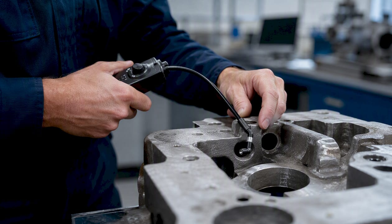
For marginal defects — indications that are close to the acceptance limit but not clearly over it — log them with a severity score and a location reference rather than forcing an immediate pass/reject decision. Tracking marginal indications across a production lot reveals process drift before it produces outright rejects. That trend data is worth more than any single disposition decision.
Know when to stop. If a passage is too tortuous for the probe to navigate without forcing, or if the surface condition (heavy scale, loose sand) prevents a clear image, the borescope has reached its limit. Escalate to X-ray CT or ultrasonic testing (UT) rather than logging a "no indication found" result that is actually a "could not inspect" result. Those two outcomes are not the same, and conflating them is a quality system failure.
Training a technician to inspection-ready status on a new part typically takes three to five supervised inspections: one to learn the insertion sequence, one to practice articulation control, one to practice image capture and documentation, and one or two to calibrate their defect recognition against known reference samples. After that, periodic inter-rater reliability checks (two inspectors reviewing the same images independently) keep judgment consistent across a team.
1800endoscope carries the probes and accessories your casting inspection needs
For casting QC teams that need a reliable source for small-diameter videoscopes, flexible probes, and inspection accessories, 1800endoscope stocks a broad range of industrial borescopes and videoscopes built for exactly this kind of work. The catalog includes HD video recording, adjustable LED illumination, and portable designs that move easily between inspection stations — features that matter when you are covering multiple part numbers across a shift.
If your application calls for a compact, portable option, the 6mm portable video endoscope is a practical starting point for galleries and passages in that diameter range, with direct monitor display and SD card recording for documentation. For teams working through probe selection for a complex geometry, 1800endoscope's sales team can help match probe diameter, working length, and articulation to your specific part. Browse the full catalog or reach out directly to discuss your inspection requirements and get a recommendation.
Sources
- Evaluation of different defect-inspection setups for injection molding parts based on the deep learning method | Scientific Reports
- What Is Non-Destructive Testing? | UTI
- Casting defect - Wikipedia