
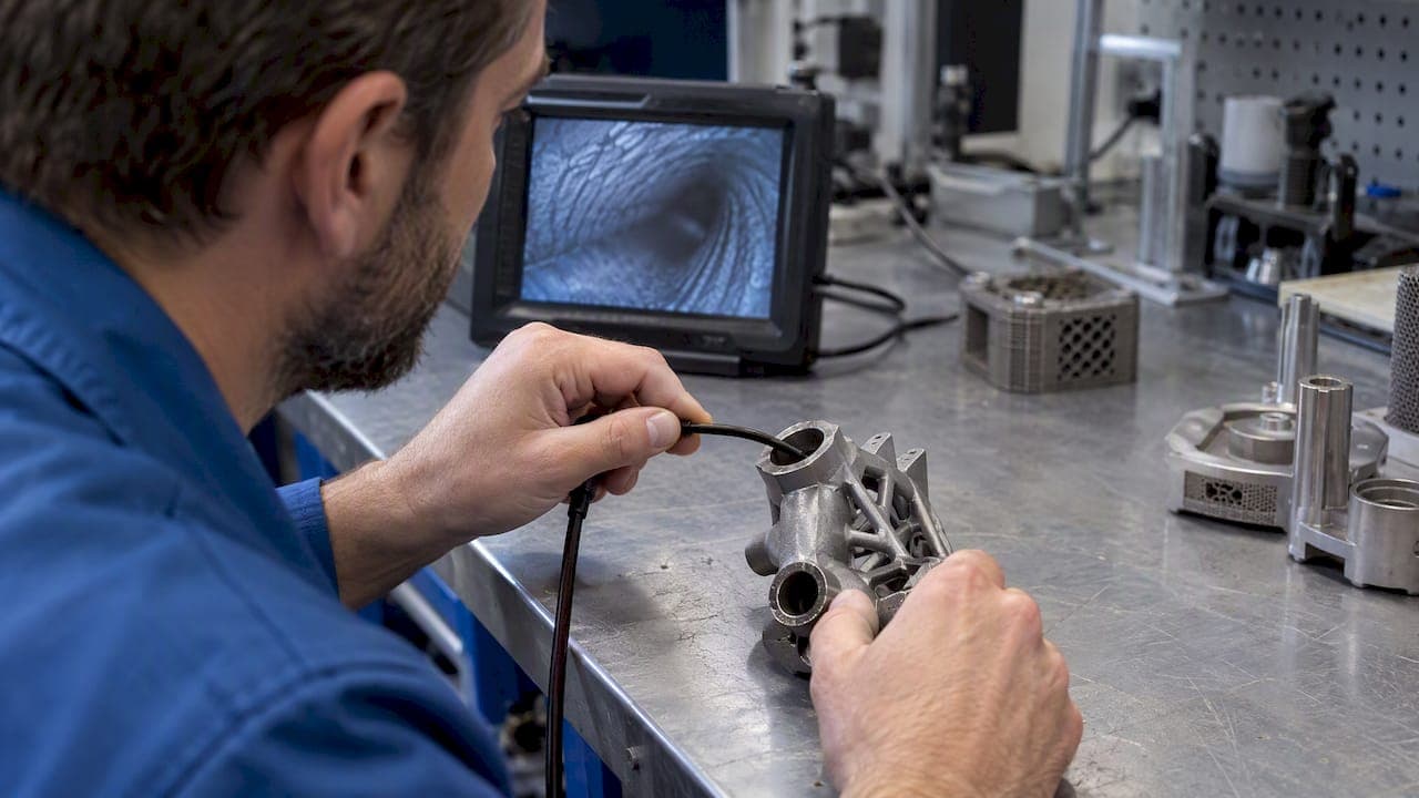
A correctly sized and configured borescope can reliably inspect internal surfaces and channels of many 3D-printed parts. Use it as part of a documented inspection routine, and pair it with volumetric NDT like XCT when subsurface flaws are suspected. ASTM Guide E3166 recognizes borescopy as a useful technique for characterizing internal passages in additively manufactured parts, and we carry the probe hardware to put that guidance into practice.
TL;DR:
- Choose micro probes under 2 mm for fine lattices and conformal channels; use 2 to 6 mm probes for larger cavities, galleries, and passages.
- Clean powder or uncured resin, remove obstructing supports, secure the part, and record access point location before inspection to reduce false indications and missed areas.
- Center the probe in straight channels, rotate fully at cavity stops, and reduce LED intensity rather than pulling the tip away to control glare.
- Save raw video and an annotated still for each indication, recording probe type, lighting, and location, then link files to the build ID immediately.
- A borescope cannot reveal subsurface porosity; use XCT for volumetric confirmation when an indication appears three dimensional or a critical part requires evidence beyond surfaces.
Table of Contents
- Choosing the right borescope type, probe diameter, and tip optics for AM parts
- How to prepare a 3D-printed part before borescope inspection
- Inspection techniques: probe paths, viewing angles, and coverage strategy
- Imaging, capture settings, and documentation best practices
- How borescope inspection complements other NDT and process-monitoring methods for AM
- Ensuring repeatability: competence, documentation templates, and automation options
- Material compatibility considerations between borescope optics and 3D printed part materials
- Limitations and common challenges of using borescopes for inspecting 3D printed bores
- Maintenance and cleaning protocols for borescopes after inspecting additive manufactured parts
- Field perspective from 1800endoscope on inspection-first workflows
- Where to find borescopes and accessories built for additive manufacturing inspection
- FAQ
- Sources
Choosing the right borescope type, probe diameter, and tip optics for AM parts
Rigid borescopes give you the sharpest image and the steadiest field of view, which makes them a strong fit for straight bores and short, line-of-sight channels common in machined-then-printed hybrid parts. Flexible video borescopes trade some resolution for reach: they bend through the curved lattices, conformal cooling channels, and internal supports that additive manufacturing makes possible in the first place. A comparison of rigid, flexible, and videoscope options walks through the tradeoffs in more depth if you're matching hardware to a new part family.
Probe diameter matters more in AM work than in traditional pipe or engine inspection, since lattice structures and internal channels can run smaller than 3 mm. Micro probes under 2 mm fit intricate internal lattices and conformal channels, while 2 to 6 mm probes handle larger cavities, fuel galleries, and heat exchanger passages. Reach is the other constraint: a probe that's long enough for the part but too limp to control will drift off centerline and miss the walls you came to inspect.
Tip optics change what you can actually see:
- Forward-viewing tips work best for axial passes down straight channels.
- Side-viewing or angled tips reveal wall detail in short, wide cavities where a straight view only shows the far end.
- Stereo or measurement tips let you size an indication rather than just flag it.
Round out the kit with a steerable shaft for multi-bend geometries, a protective sleeve to keep sharp internal edges from scoring the probe, and an adjustable LED light source, since fixed brightness tends to wash out matte, light-colored polymer and powder-bed metal surfaces alike.
Pro Tip: Keep one micro probe and one standard-diameter probe staged together; switching mid-inspection costs less time than re-fixturing a part you've already opened up.
How to prepare a 3D-printed part before borescope inspection
Internal surfaces hide defects behind debris as often as they hide them behind geometry, so preparation decides how much you'll actually see.
- Depowder or clean the part fully; loose powder in a metal powder-bed part or uncured resin in a stereolithography part will scatter light and mimic porosity on camera.
- Remove any support structures that block the planned viewing path, noting which supports were load-bearing before you cut them.
- Use existing access ports where the design provides them, or add a minimal access point, then record its exact location and orientation for later reference.
- Fixture the part securely so it can't shift mid-pass, since movement during a probe run is the most common cause of a missed section on a second inspection.
- Avoid introducing new marks while opening access points: a drill burr or a scraped edge is easy to mistake for a print defect on camera.
Skip cosmetic treatments like matte coatings unless you're certain they won't mask the very defect signature you're trying to characterize.
Inspection techniques: probe paths, viewing angles, and coverage strategy
Coverage strategy depends on geometry. Run axial centerline passes down straight channels and conformal cooling paths, keeping the tip centered to avoid false shadows from an off-axis view. Switch to circumferential sweeps inside larger cavities, rotating the probe through a full revolution at each stop rather than advancing and rotating at the same time, which tends to leave gaps. Pockets and blind cavities need multi-angle passes: one centerline look rarely shows a pocket's full wall.
Working distance consistency matters as much as the path itself. A tip held too close overexposes the surface directly beneath it and underexposes everything else in frame; held too far, you lose the resolution needed to catch a hairline layer-delamination line. A slow tilt-and-sweep motion, rather than a straight pass, is what typically reveals underfill at layer boundaries, since the defect only becomes visible at certain light angles.
Glare is a persistent problem on both polished metal and semi-gloss polymer prints. Dial back LED intensity rather than pulling the tip away, and use a diffuser sleeve where your light source supports one.
- Use a forward-viewing tip for channel centerlines, then switch to side-viewing for cavity walls.
- Slow the probe speed near any suspected indication rather than near the end of a planned pass.
- Re-run a pass at a different rotational offset whenever lighting conditions suggest an indication might be a reflection.
Pro Tip: When an indication looks three-dimensional, such as a crack or a void with depth rather than a flat surface mark, that's the signal to stop and schedule XCT before disposition, not to call it from the borescope image alone.
Our guide to flexible borescope technique covers probe handling in more detail for technicians building this skill for the first time.
Imaging, capture settings, and documentation best practices
Record video at the highest resolution your system supports reliably, since a dropped frame at the exact moment of an indication means a re-inspection. Capture an annotated still at every indication rather than relying on the video alone to carry disposition information later. Lock white balance and exposure where your borescope allows it; auto-exposure that hunts for the right setting mid-pass produces footage that's hard to review frame by frame.
Map every indication back to part geometry using encoder marks, a ruler reference, or a fixed distance marker visible in frame, then timestamp the file and link it to the build ID before you move to the next part. A minimum file naming convention, part ID, build number, inspector initials, probe used, and date, saves far more time at audit than it costs at capture.
- Save raw video and an annotated still for every indication, not one or the other.
- Record probe diameter, tip type, and lighting setting alongside the footage.
- Link each file to its build ID at the time of capture, not afterward.
Encoder-driven, AI-assisted borescope systems have been shown to reduce inspection time roughly fivefold in tube-like geometries while improving traceability, a meaningful gain if your shop runs high part volumes. Where dimensional evidence matters, a measurement-capable or stereo borescope lets you size an indication directly rather than estimating it by eye; our overview of advanced videoscope features covers what that hardware adds.
How borescope inspection complements other NDT and process-monitoring methods for AM
Borescopy's strengths are speed, low cost, and direct visual detail on internal surfaces: you see underfill, delamination lines, support scarring, and debris exactly as they appear, without modeling or reconstruction. What it can't do is see through a wall. A borescope shows you the surface of a bore, not the porosity sitting a millimeter beneath it, so it's not a substitute for volumetric methods.
- Pair a borescope pass with XCT when a surface indication needs volumetric confirmation.
- Pair in-process optical monitoring with acoustic emission sensing to catch transient extrusion events that a camera alone would miss.
- Use borescope findings to decide where to focus a more expensive XCT scan, rather than scanning the full part.
Recent work on endoscopic vision systems built into a printer head shows that cameras mounted close to the nozzle can catch layer-level defects like stringing and under-extrusion in real time, feeding a classification model that supports corrective action during the build itself. A related digital-thread framework takes this further: fusing optical imaging with acoustic emission sensors lets a closed-loop system detect a defect and adjust flow rate mid-print, which points toward where in-process AM monitoring is headed. ASTM Guide E3353 extends this same multimodal thinking to post-build AM NDT procedures, treating borescopy as one input among several rather than a standalone qualification method.
Ensuring repeatability: competence, documentation templates, and automation options
Two technicians inspecting the same bore can report different results if neither documents their method, which is the single biggest source of variability in borescope work.
- Record probe path, lighting level, working distance, and camera settings for every inspection, not just the ones that find something.
- Use a simple reporting template: part and build ID, probe type and diameter, passes performed, each indication with location and image, and final disposition.
- Schedule periodic blind validation tests, where a technician inspects a part with a known, undisclosed defect, alongside peer review of saved footage to catch drift in judgment over time.
- Consider encoder-driven or automated acquisition for high-volume lines; the upfront cost buys meaningfully better repeatability than manual passes alone.
Pro Tip: Store your reporting template as a locked form, not a blank document each inspector fills differently; consistent fields matter more than how detailed any single field is.
Material compatibility considerations between borescope optics and 3D printed part materials
Borescope optics and the part material interact more than technicians often expect. Metal powder-bed parts, particularly those in titanium or nickel alloys, tend to have as-built internal surfaces with high reflectivity in some spots and near-matte roughness in others, which makes consistent exposure harder than on a smooth, machined bore. Dial lighting down for the reflective facets and accept a slightly longer dwell time on the rougher ones rather than trying to find one setting for the whole pass.
Polymer parts, especially translucent resins and lightly pigmented filaments, can scatter light internally rather than reflecting it cleanly off the surface, which softens edge detail on fine features like thin wall sections or small internal ribs. A tighter working distance and a diffused light source usually recovers the detail that a direct, high-intensity LED would blow out.
Chemical compatibility is a secondary but real concern. Uncured resin residue or release agents left on a printed part can transfer onto a probe's optical window or protective sleeve, so wipe down the part before insertion rather than relying on the sleeve to stay clean through a full inspection run. Powder residue, particularly fine metal powder, is abrasive enough to scratch an unprotected lens over repeated contact, which is the main reason a protective sleeve earns its place in the kit for powder-bed work specifically.
None of this changes the basic inspection technique; it changes how you set lighting and exposure before you start, and that setup time is worth the extra minute it costs.

Limitations and common challenges of using borescopes for inspecting 3D printed bores
The most important limitation is one we've already stated directly: a borescope sees surfaces, not volumes. Subsurface porosity, internal lack-of-fusion in a metal part, or a void sitting beneath an otherwise clean-looking wall will not show up on a borescope image no matter how good the lighting or optics are. That's a detection ceiling, not a technique problem, and it's why pairing with XCT matters for critical parts.
Access is the second recurring challenge. Lattice structures and organic internal geometries, the kind additive manufacturing makes possible precisely because they couldn't be machined, sometimes have no straight path for even a flexible probe to follow. A channel that curves sharply enough can exceed a probe's bend radius, leaving a section of the part effectively uninspectable without redesigning the access port.
Surface roughness native to the AM process, particularly on as-built metal powder-bed surfaces, creates a texture that can look like a defect to an inexperienced eye. Distinguishing an actual crack from a shadow cast by normal layer-stepping roughness takes practice, which is why operator competence and documented comparison images matter more here than in traditional machined-part inspection. Finally, probe diameter itself is a hard limit: a channel narrower than any probe in your kit simply can't be inspected this way, full stop, and that constraint should factor into design reviews before parts reach the inspection floor, not after.
Maintenance and cleaning protocols for borescopes after inspecting additive manufactured parts
Metal powder residue is the main threat to probe longevity after AM inspection work. Wipe the full length of the insertion tube with a lint-free cloth immediately after withdrawal, before any residual powder has a chance to dry onto the sheath, and inspect the protective sleeve for scoring that could compress onto the optical window on the next use.
Clean the distal tip lens with a manufacturer-approved optical cleaning solution rather than a general-purpose solvent, since some polymer print residues respond poorly to harsh chemical cleaners and can leave a haze that's hard to remove later. Check the light source connector and any articulation cables for powder ingress, particularly on systems used across both metal and polymer AM parts in the same shift, since contamination carried from one job to the next is an easy way to introduce a false indication on an unrelated part.
Store probes straight or in their designed storage coil, never kinked, and log cleaning and inspection dates alongside the part inspection records themselves. A probe maintained on a documented schedule stays measurement-reliable for longer, which matters directly for any shop depending on stereo or measurement-capable tips for dimensional disposition.
Field perspective from 1800endoscope on inspection-first workflows
Catching an internal defect with a borescope before a part reaches final qualification saves far more time than finding it after. We see it most often on channel geometries: a five-minute internal check prevents a scrapped part and a rebuilt schedule. Our field guide to industrial borescope uses and the inspection FAQ and procedures page cover more real-world examples.
For volumetric confirmation work beyond what a borescope can show, we've seen inspection teams pair this routine with 3D scanning and CMM-based quality workflows to tie dimensional data back to the same part record.
— Endoscope
Where to find borescopes and accessories built for additive manufacturing inspection
Probe hardware suited to these inspection needs includes micro probes under 2 mm for fine internal lattices, larger-diameter portable videoscopes for bigger cavities and channels, and protective sleeves and adjustable light sources designed to keep images usable on polymer and metal AM parts alike.
If you're matching a probe to a specific channel geometry or reach requirement, the industrial borescope and micro probe category lists diameter and reach specs side by side, and it is possible to confirm the right combination before ordering. When a dimensional question comes up mid-project, our portable SD-card recording videoscope is a practical option for shops that need documented footage without a large capital outlay. Reach out through our catalog page to compare lighting and accessory options alongside the probes themselves.
FAQ
Can a borescope detect internal porosity in a 3D-printed metal part?
No. A borescope only shows surfaces it can see directly, so it will miss porosity sitting beneath a bore wall. ASTM Guide E3166 treats borescopy as a complement to volumetric methods like XCT, not a replacement for them.
What probe diameter do I need for small internal lattice channels?
Micro probes under 2 mm typically fit the fine internal lattices and conformal cooling channels common in additive manufacturing, while larger 2 to 6 mm probes suit bigger cavities and galleries. The right choice depends on your narrowest access point, since a probe that doesn't physically fit can't inspect that section at all.
How do I document a borescope indication for traceability?
Capture an annotated still image at the indication alongside the full video pass, and record the probe type, lighting setting, and working distance used. Link the file to the part's build ID and timestamp it, since this is what lets you compare the same location on a future inspection.
Should I use a borescope or XCT for a newly printed part?
Start with a borescope pass to check accessible internal surfaces for visible defects like underfill or delamination, since it's faster and lower cost. Escalate to XCT when a surface indication looks three-dimensional or when the part's criticality calls for volumetric confirmation beyond what an internal camera can show.
Can automated or encoder-driven borescopes improve inspection consistency?
Yes. Encoder-driven systems with AI-assisted analysis have been shown to cut inspection time roughly fivefold on tube-like geometries while improving repeatability compared to manual probe handling. They represent a higher upfront cost but a meaningful gain for shops running high inspection volumes.
Sources
- Real-Time Monitoring of 3D Printing Process by Endoscopic Vision System Integrated in Printer Head
- A digital thread approach for real-time defect correction in polymer additive manufacturing
- Automated borescope inspection with AI support for visual testing
- ASTM Guide E3166 — NDT procedures for metal additive manufacturing