
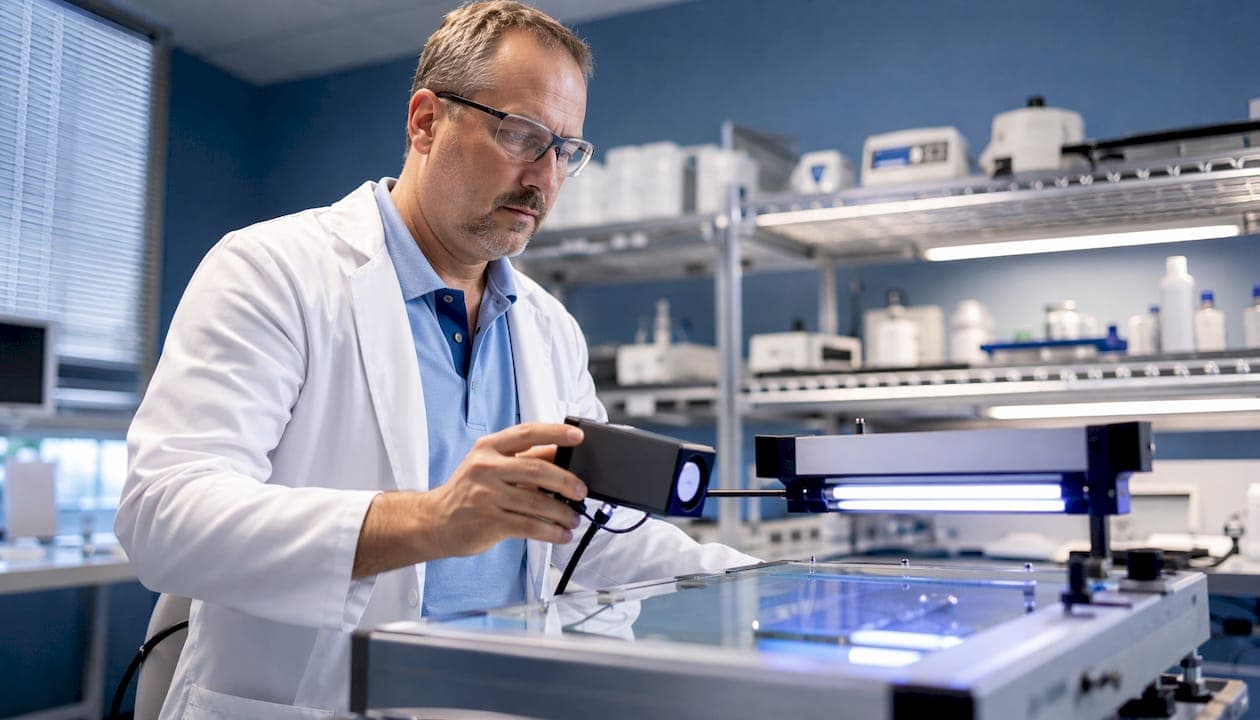
Before you switch on a UV-A lamp for a liquid penetrant or magnetic particle inspection, two ASTM standards control what that lamp must do: ASTM E2297-23 and ASTM E3022-18. Together they define the wavelength band, irradiance floor, visible-emission limits, and measurement geometry that determine whether your light source is fit for use. Scope lighting standardization in NDT is not a paperwork exercise — a lamp that reads fine on the label but drifts spectrally or loses uniformity will let defects walk right past you.
Before every inspection, verify these three things:
- Irradiance at 38.1 cm (15 in): The commonly cited acceptance target under ASTM E2297-23 is 1000 μW/cm² or greater for UV-A fluorescent inspections. Measure with a calibrated UV radiometer at that exact distance.
- Visible emission: Confirm emission above 400 nm is within the limits your procedure specifies. Excess visible light bleeds into the fluorescent contrast and kills indication visibility.
- Documentation on hand: Certificate of Conformance (CoC) or Validation Report (VR), last calibration date and lab accreditation (ISO/IEC 17025 or NIST traceability), and the lamp's serial number. No paperwork, no inspection.
Table of Contents
- What ASTM E2297-23 and E3022-18 actually require from you
- Other standards and frameworks technicians need to know
- How to measure the metrics that actually matter
- How to calibrate and validate your lamps properly
- How to read your measurements and make a go/no-go call
- What LED lamps do differently — and why it matters for calibration
- Pre-inspection field checklist for lamp compliance
- What auditors expect to find in your records
- Key Takeaways
- Why lighting controls are the most under-enforced part of NDT quality
- NDT light sources and borescopes built for compliance
- Useful sources
What ASTM E2297-23 and E3022-18 actually require from you
ASTM E2297-23 is the primary standard governing how UV-A and visible light sources are selected, measured, and used in liquid penetrant (PT) and magnetic particle (MT) examinations. It standardizes the measurement geometry, meter types, and viewing conditions — not just the lamp itself.
The standard's key technical requirements for technicians:
Spectral band: UV-A lamps must emit in the 320–400 nm band, with peak output typically near 365 nm. Emission outside this band, particularly above 400 nm into visible wavelengths, is a compliance concern because it reduces the contrast between the fluorescent indication and the background.
Irradiance threshold: The commonly cited benchmark is measured at a specified minimum irradiance level from a defined distance. Your written procedure may specify a higher value — always defer to the more stringent requirement.
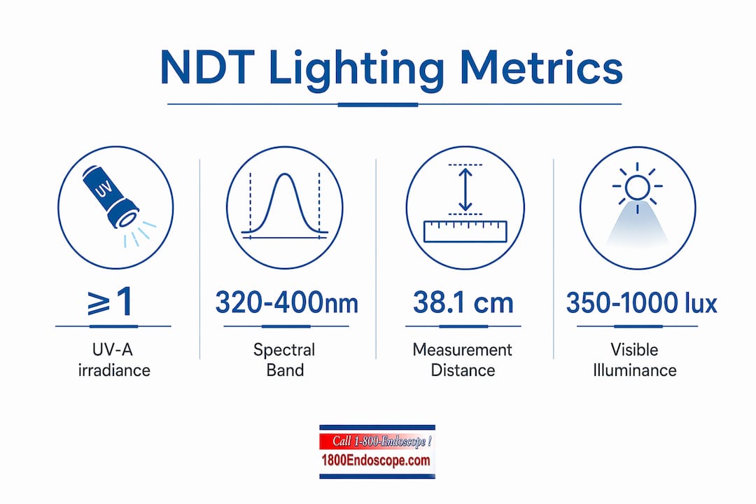
Visible emission warning: ASTM E2297-23 explicitly flags that visible emission above 400 nm can reduce fluorescent indication visibility. This is not a theoretical concern. A lamp with even modest visible leakage in a darkened inspection booth will wash out the glow from fine cracks.
UV fade: The standard also warns that excessive UV-A intensity causes UV fade in fluorescent penetrants, where prolonged exposure degrades the indication. Higher is not always better. Targeting the specified range, rather than maximizing output, protects indication integrity.
ASTM E3022-18 functions as a companion document focused on UV-A lamp performance and safety. Suppliers reference it when issuing CoCs and validation documentation. Technicians should request that any lamp CoC explicitly states conformance to ASTM E3022-18 for performance and safety parameters.
Other standards and frameworks technicians need to know
ASTM E2297-23 and E3022-18 do not operate in isolation. Depending on your employer, contract, or certification body, several other documents shape what you must do and prove.
- ISO 9712:2021: The international standard for NDT personnel qualification and certification. It does not set lighting metrics, but it defines who is authorized to perform and approve NDT work. Auditors checking your inspection records will want to see that the technician performing the lighting verification holds the appropriate qualification level under ISO 9712 or an equivalent national scheme.
- ASNT CP-189 and SNT-TC-1A: The dominant employer-based certification frameworks in the U.S. Employer procedures written under these schemes typically reference ASTM lighting limits as the acceptance criteria technicians must meet and document. CP-189 is the more prescriptive of the two; SNT-TC-1A gives employers more flexibility to define their own requirements.
- ICNDT guidance: ICNDT recommends harmonization around ISO 9712 and requires that certification bodies meet ISO/IEC 17024 or equivalent. For technicians working internationally or on contracts with multinational clients, ICNDT-aligned certification adds audit credibility.
- EN ISO 3059: The European equivalent for viewing conditions in PT and MT. If your procedure references EN ISO 3059 alongside ASTM, the more stringent requirement governs. Some U.S. aerospace and energy contracts specify both.
- ASME and buyer specifications: ASME Section V (Article 6 for PT, Article 7 for MT) and owner/client specifications frequently impose lighting requirements that exceed the ASTM minimums. Always read the contract-specific code before assuming ASTM alone is sufficient.
A practical example: an employer procedure written under SNT-TC-1A might state "UV-A irradiance shall meet ASTM E2297-23 requirements" while relying on ISO 9712 for personnel qualification and ASME Section V for the overall examination method. The technician must satisfy all three simultaneously.
How to measure the metrics that actually matter
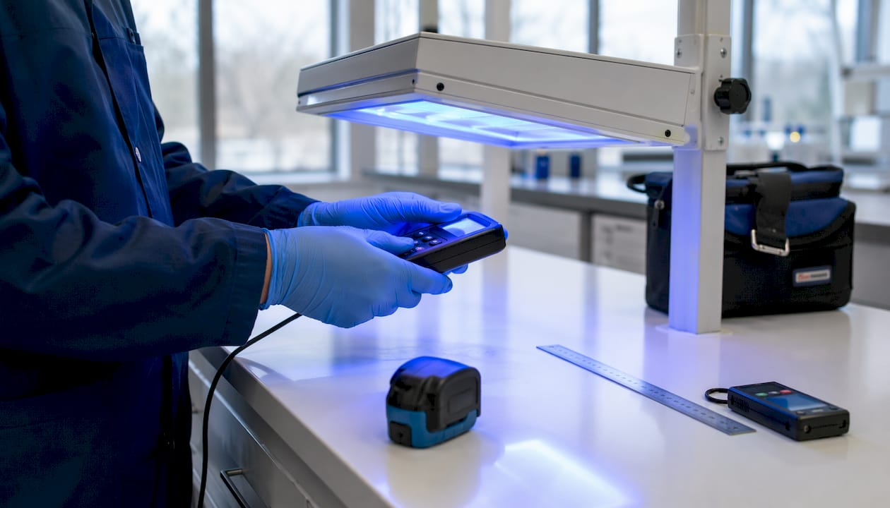
Scope lighting standardization in NDT comes down to four measurable quantities. Get these right and your lamp is compliant. Miss one and the whole inspection is suspect.
| Metric | Unit | Typical Acceptance Target | Recommended Instrument |
|---|---|---|---|
| UV-A irradiance | μW/cm² | ≥1000 at 38.1 cm | Calibrated UV-A radiometer (field) or spectroradiometer (lab) |
| Visible illuminance | lux or fc | ≤20 lux in darkened booth (PT/MT); ≥1000 lux for critical visual tasks | Calibrated photometer |
| Spectral distribution | nm (peak and range) | Peak ~365 nm; emission band 320–400 nm; visible leakage per procedure limit | Spectroradiometer (lab-grade) |
| Uniformity | % variation across field | Per procedure; typically ≤20–30% variation across inspection area | UV radiometer, multiple-point grid |
Measurement geometry matters as much as the number itself. ASTM E2297-23 specifies that irradiance is measured at 38.1 cm (15 in) from the lamp face, with the meter's sensor oriented perpendicular to the beam axis. Changing the distance by even a few centimeters changes the reading significantly because irradiance follows an inverse-square relationship with distance. Always record the exact distance used.
For visible illuminance, some guidance cites ranges around 350 lux for general visual inspection and 1000 lux for critical tasks, though your NDT procedure or contract code may specify higher. In a darkened PT or MT booth, the goal is the opposite: minimize ambient visible light to preserve fluorescent contrast.
Pro Tip: A field UV radiometer is sufficient for routine pre-inspection checks, but it cannot tell you whether the lamp's spectral distribution has shifted. If a lamp passes the irradiance check but you notice reduced fluorescent brightness or technicians are reporting faint indications, send it to a lab for spectroradiometric verification. Spectral shift is the failure mode field meters miss.
Understanding how light sources drive accuracy in scope-based NDT helps you connect these metrics to real detection outcomes, not just paperwork compliance.
How to calibrate and validate your lamps properly
Calibration is not just about getting a sticker on the lamp. It is about generating traceable evidence that your light source was performing within specification on a known date, measured by a qualified instrument, at a documented geometry.
Step-by-step calibration workflow
- Record the lamp ID and serial number before anything else. Every calibration record must tie back to a specific physical unit.
- Perform a field check using your calibrated field radiometer at the standard 38.1 cm distance. Log the reading, the meter's serial number, and the date.
- Assess against your calibration trigger criteria (see intervals below). If the lamp is due for lab calibration or has failed a field check, pull it from service.
- Ship to an ISO/IEC 17025-accredited laboratory for full spectroradiometric calibration. The lab must use a spectroradiometer traceable to NIST or an equivalent national metrology body.
- Receive and review the CoC or Validation Report. Confirm it includes: calibration date, lab accreditation number, measurement geometry (distance and angle), instrument make/model/serial, measured irradiance and spectral data, and a pass/fail statement against the applicable standard.
- Log the certificate in your quality system and attach it to the lamp's asset record. Update the calibration sticker on the lamp with the new date and due date.
Calibration intervals
- Mercury vapor and fluorescent UV lamps: Annual calibration is the common baseline, with field checks before each inspection campaign.
- LED UV-A lamps: Many programs now require calibration every 6 months for high-duty lamps, given the subtlety of LED degradation modes. Some high-criticality contracts require quarterly checks.
- Out-of-cycle triggers: Any drop in irradiance during a field check, visible emission that appears to have increased, physical damage to the lamp housing or filter, or a lamp that has been dropped or subjected to thermal shock.
What a valid calibration certificate must include
- Calibration date and expiration/next-due date
- Laboratory name and ISO/IEC 17025 accreditation number
- Measurement geometry (distance, angle, sensor orientation)
- Instrument make, model, and serial number
- NIST traceability statement
- Measured irradiance value(s) and spectral data
- Pass/fail determination against the referenced standard (ASTM E2297-23 and/or E3022-18)
- Lamp serial number and asset ID
A certificate missing any of these items is incomplete for audit purposes. Send it back.
The light source calibration process involves more nuance than most technicians expect the first time they go through it — particularly around instrument selection and traceability documentation.
How to read your measurements and make a go/no-go call
The irradiance reading from your field meter is not just a number to log. It is a binary decision point.
The threshold: Under ASTM E2297-23, the specified minimum irradiance for fluorescent PT and MT inspections is 1000 μW/cm² at 38.1 cm. Your procedure may specify higher. If it does, the procedure wins.
Key figure: The irradiance floor for UV-A fluorescent inspections under ASTM E2297-23 is specified at a defined value at a set distance. Readings below this value require immediate action before the inspection proceeds.
Decision flow for borderline readings:
- Reading is at or above threshold: Proceed. Document the reading, meter serial, distance, and date.
- Reading is 5–10% below threshold: Do not proceed. First, clean the lamp lens and filter — contamination is the most common cause of a marginal drop. Re-measure. If it recovers, document the cleaning and proceed. If it does not recover, remove the lamp from service.
- Reading is more than 10% below threshold: Remove from service immediately. Tag the lamp, initiate a lab calibration, and substitute a compliant unit.
- Visible emission above procedure limit: Stop. Excess visible emission above 400 nm invalidates fluorescent contrast regardless of whether irradiance is nominal. The lamp must be evaluated for filter degradation or spectral shift before use.
For borescope-based visual inspections, light intensity's role in flaw detection follows similar logic: a lamp that reads within spec on paper but delivers uneven illumination inside a bore will produce shadows that mask surface discontinuities.
Measurement uncertainty is real. Field radiometers carry calibration uncertainty, typically ±5–10% depending on the instrument and its last calibration date. When a reading sits close to the threshold, factor that uncertainty in conservatively. If the reading minus the instrument uncertainty falls below the threshold, treat it as a fail.
What LED lamps do differently — and why it matters for calibration
LED UV-A lamps have largely replaced mercury vapor sources in most U.S. NDT shops. They are more energy-efficient, produce less heat, and last longer. But their failure modes are fundamentally different, and those differences change how you calibrate and monitor them.
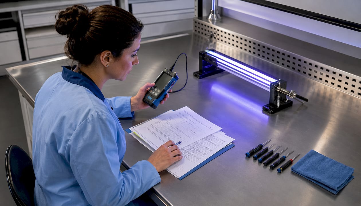
Chip degradation is gradual and often invisible to the naked eye. An LED array can lose 15–20% of its output over thousands of hours while still appearing to glow brightly. A field radiometer catches this; a visual inspection does not.
Phosphor shifts are the subtler problem. Some UV-A LEDs use phosphor conversion layers that can shift peak emission wavelength with age or thermal stress. The lamp may still read acceptable irradiance at 365 nm, but if the peak has drifted toward 380–395 nm, the excitation efficiency for common fluorescent penetrants drops. You will see reduced indication brightness before you see a failed irradiance reading.
Non-uniform fields are a particular LED risk. Unlike mercury vapor lamps, which produce a relatively diffuse output, LED arrays can develop localized dimming as individual chips degrade at different rates. The center of the beam may still pass the irradiance check while the edges fall below threshold. A single-point measurement at the beam center will miss this entirely.
Key concern: LED failure modes like chip degradation and phosphor shifts can be subtle and create non-uniform light fields that compromise inspection integrity without triggering a simple irradiance alarm.
UV fade and high-intensity LEDs: High-output LED UV-A lamps can deliver irradiance well above 1000 μW/cm², which sounds like a safety margin. It is not. Prolonged exposure to very high UV-A intensity causes UV fade in fluorescent penetrants, where the indication degrades during the inspection itself. Target the specified range; do not assume maximum output is optimal.
Practical mitigation for LED lamps:
- Perform a multi-point uniformity check (at minimum, center and four quadrants at 38.1 cm) at acceptance and at each calibration interval.
- Add spectral distribution measurement at acceptance and annually, even if irradiance checks pass.
- Shorten calibration intervals for high-duty lamps (more than 4 hours of daily use) to every 6 months.
- Record lamp operating hours if the unit has an hour meter, and use hours as a secondary trigger for out-of-cycle calibration.
Pro Tip: When accepting a new LED UV-A lamp into service, take a baseline spectral measurement and photograph the uniformity map. Store both with the lamp's asset record. When the lamp eventually drifts, you will have a documented baseline to compare against rather than guessing whether the shift is new.
For a deeper look at LED illumination behavior in borescopes, the same degradation principles apply whether the scope is used for visual NDT or fluorescent inspection support.
Pre-inspection field checklist for lamp compliance
Run this before every inspection campaign. It takes under five minutes and it is the difference between a defensible record and a failed audit.
Step-by-step pre-inspection verification
- Verify the CoC/VR and calibration date. Confirm the lamp's calibration certificate is current, the issuing lab holds ISO/IEC 17025 accreditation or NIST traceability, and the certificate references ASTM E2297-23 or E3022-18.
- Check the lamp serial number against the certificate. If the serial on the lamp does not match the certificate, stop. Do not use the lamp until the discrepancy is resolved.
- Warm up the lamp per the manufacturer's specification (typically 5–10 minutes for UV-A sources). Measuring before full warm-up produces artificially low readings.
- Measure irradiance at 38.1 cm using your calibrated field radiometer. Orient the sensor perpendicular to the beam. Record the reading.
- Perform a uniformity check. Measure at the beam center and at least four off-center points. Flag any point that reads more than 20–30% below the center value (or per your procedure's uniformity tolerance).
- Check for visible emission. In a darkened area, visually confirm the lamp does not produce significant white or blue-white light. If your procedure requires a measured visible-light check, use a calibrated photometer.
- Record everything on your field form and initial it.
Minimal field form — required fields
| Field | What to Record |
|---|---|
| Lamp ID / Serial | Asset tag and serial number from the lamp housing |
| Meter Used | Make, model, and serial number of the field radiometer |
| Meter Last Calibration | Date of the meter's last calibration |
| Irradiance Reading | Measured value in μW/cm² and distance used |
| Uniformity Notes | Center and off-center readings, or "uniform — no anomalies" |
| Visible Emission | Pass / Fail / Not checked (with reason) |
| Environmental Notes | Ambient temperature, booth conditions if relevant |
| Operator Initials | Technician performing the check |
| Pass/Fail Decision | Go / No-go with action taken if no-go |
When to stop and escalate: Below-threshold irradiance after cleaning, visible emission that cannot be explained by ambient light, any non-uniformity that exceeds your procedure's tolerance, or physical damage to the lamp housing, filter, or cable. Tag the lamp out of service, document the reason, and notify your Level III or quality supervisor.
What auditors expect to find in your records
An auditor reviewing your NDT lighting compliance is looking for a chain of evidence: from the lamp in your hand, back through its calibration history, to a traceable measurement standard. Gaps in that chain are findings.
Traceability matters: Calibration certificates referencing ISO/IEC 17025 accreditation or NIST-traceable standards significantly reduce audit friction and are frequently required by owner/client specifications.
The minimum document set for each lamp:
- Current calibration certificate (CoC or VR) with lab accreditation number
- Lamp serial number and asset tag record
- Last field-check record with operator initials and date
- Meter calibration certificate (for the field radiometer used)
- Reference to the procedure or standard the lamp was verified against
File naming and retention: A simple convention prevents lost records. Use the format LampID_CoC_YYYYMMDD.pdf for calibration certificates and LampID_FieldCheck_YYYYMMDD.pdf for field records. Store electronic copies in your quality management system and keep paper backups for at least the duration of the contract or the inspection record retention period, whichever is longer. Many aerospace and energy contracts require 10-year retention.
What auditors specifically look for on the certificate:
- The lab's ISO/IEC 17025 accreditation number or scope of accreditation
- An explicit NIST traceability statement (not just "traceable to national standards" — the specific chain should be stated)
- Instrument serial numbers for every measurement device used
- The measurement geometry (distance, angle, sensor orientation) used during calibration
- A pass/fail determination, not just raw numbers
ISO 9712:2021 and ASNT standards both reinforce that documentation traceability is as much a part of competent NDT practice as the measurement itself. An inspection performed with a compliant lamp but missing traceable records is not a defensible inspection.
Key Takeaways
ASTM E2297-23 sets the irradiance floor, spectral limits, and measurement geometry that every UV-A lamp used in U.S. NDT must meet, and no inspection is defensible without a traceable CoC from an ISO/IEC 17025-accredited lab on file.
| Point | Details |
|---|---|
| Irradiance floor | Measure the irradiance must meet the required minimum level at the specified inspection distance; readings below this require immediate action. |
| Spectral leakage control | Visible emission above 400 nm invalidates fluorescent contrast; check it at every calibration and flag any visible-light anomaly in the field. |
| Traceable calibration paperwork | Every lamp needs a current CoC or VR from an ISO/IEC 17025-accredited lab with NIST traceability stated explicitly. |
| LED-specific monitoring | Add multi-point uniformity checks and spectral distribution measurements for LED lamps; chip degradation and phosphor shifts are not caught by irradiance alone. |
| 1800endoscope equipment | 1800endoscope's serial-tracked NDT borescopes and light sources are specified with wavelength control and measured irradiance outputs to support ASTM-aligned field verification. |
Why lighting controls are the most under-enforced part of NDT quality
The inspection community has spent decades refining penetrant chemistry, magnetic particle carrier fluids, and personnel qualification schemes. Lighting gets treated as infrastructure — something you set up once and forget. That is the wrong frame.
A lamp that was compliant at last year's calibration may have drifted enough by month eight to reduce fluorescent indication brightness by 20–30%. The technician performing the inspection has no way to know that from visual observation alone. The penetrant is still glowing. The indications are still visible. But the faint ones, the tight fatigue cracks and the shallow porosity, are gone. The inspection passes. The part goes into service.
The field check before each inspection is not bureaucratic overhead. It is the only control that catches in-service drift between calibration intervals. A five-minute irradiance measurement and a quick paperwork review is a small investment against the cost of a missed defect.
There is a real tension between inspection throughput and verification rigor. Technicians under production pressure skip the warm-up, measure at the wrong distance, or log the previous reading rather than a fresh one. The checklist in this guide is deliberately minimal — it covers only what actually changes between inspections and what auditors actually check. Cutting it further does not save meaningful time; it just removes the last line of defense.
NDT light sources and borescopes built for compliance
Meeting ASTM E2297-23 and E3022-18 in the field starts with equipment that is specified to support those checks from day one. 1800endoscope's NDT borescopes and inspection light sources are serial-tracked units with documented irradiance outputs and wavelength specifications, so you have the manufacturer data you need when building your CoC file and asset records.
For technicians who need a portable, self-contained inspection system that pairs scope illumination with direct video capture, the portable 6mm airway inspection system gives you HD video recording and SD card documentation in a single unit — useful when you need to photograph meter readings and scope views as part of your field evidence package. Whether you are building out a new inspection program or replacing aging lamp inventory, 1800endoscope's catalog covers the hardware side of compliance-ready scope lighting. Browse the full range or contact the team directly at 1800endoscope.com to discuss which units fit your procedure requirements.
Useful sources
- ASTM E2297-23: The primary standard for UV-A and visible light source use in PT and MT. Contains measurement geometry, irradiance thresholds, spectral requirements, and warnings about visible emission and UV fade. Every technician performing fluorescent PT or MT should have access to this document.
- ASTM E3022-18: Companion standard covering UV-A lamp performance and safety for NDT applications. Suppliers reference it in CoCs and validation documentation. Available through ASTM International.
- ASTM Nondestructive Testing Standards: The full ASTM NDT standards catalog, including E2297, E3022, and related guides for radiographic, ultrasonic, and electromagnetic methods.
- ISO 9712:2021: The international standard for NDT personnel qualification and certification. Required reading for understanding audit expectations around who performs and approves lighting verification.
- ASNT Standards: CP-189 and SNT-TC-1A define employer-based certification frameworks in the U.S. and set the context for how lighting verification responsibilities are assigned in written procedures.
- ICNDT Guidelines 2024: Guidance on harmonization around ISO 9712 and requirements for certification bodies. Relevant for technicians working on international contracts or multinational audits.
- ISO/IEC 17025 accreditation directory: Use the ILAC MRA partner directory or A2LA's online database to verify that a calibration laboratory holds current accreditation before sending lamps for calibration.
- Your employer's written procedure: Always the first document to check. Employer procedures frequently impose requirements stricter than the ASTM minimums, and the procedure governs what you must document and prove.