

Light intensity is defined as the measurable luminous power per unit area striking an inspection surface, and it is the single most influential variable in flaw detection accuracy. Insufficient intensity leaves defects invisible against their background. Too much intensity washes out contrast and creates veiling glare that masks the very flaws you are trying to find. The role of light intensity in flaw detection spans every inspection discipline, from Boeing STP 0637 aerospace surface audits requiring 100 foot-candles to GFSI food manufacturing benchmarks set at 540 lux, to veterinary endoscopy where internal tissue contrast depends entirely on the light source at the tip of the scope. Getting intensity right is not optional. It is the foundation of every reliable inspection outcome.
How does light intensity affect defect visibility?
Lighting determines defect visibility more directly than camera resolution. A high-resolution sensor cannot recover contrast that poor illumination never created. This is the most underappreciated fact in inspection engineering, and it applies equally to a borescope inside a turbine and a veterinary endoscope inside an equine airway.
The physics are straightforward. A defect becomes visible when it reflects or absorbs light differently than the surrounding surface. Optimal light intensity amplifies that difference. Too little intensity compresses the tonal range, making shallow cracks or surface irregularities disappear into background noise. The relationship between intensity and contrast is not linear. There is a threshold below which defects simply do not appear, and a ceiling above which they get erased by overexposure.

Excessive brightness masks defects through two mechanisms: washout and veiling glare. Washout occurs when the sensor or the human eye receives more light than it can differentiate, collapsing fine tonal gradients into a uniform bright field. Veiling glare is a secondary effect where scattered light from a bright source fills in shadows that would otherwise define a crack edge or pit boundary. Both effects produce false negatives, the most dangerous outcome in any inspection process.
Surface type changes the equation significantly. Matte surfaces scatter light diffusely, making intensity the primary control variable. Reflective or polished surfaces introduce specular reflection, where a direct bright source creates a mirror-like hotspot that obliterates the area underneath it. On those surfaces, angle of incidence and diffusion matter as much as raw intensity.
- Contrast enhancement: Intensity set at the correct level for the surface type maximizes the tonal difference between a defect and its background.
- Angle of incidence: Raking light at a low angle casts shadows from surface irregularities, making them visible on matte surfaces.
- Diffuse versus point sources: Point sources create specular hotspots on shiny surfaces; diffuse dome lighting spreads illumination uniformly.
- Uniform coverage: Uneven lighting creates false shadows that mimic defects or hide real ones, producing both false positives and false negatives.
Pro Tip: When inspecting a reflective metal surface, reduce intensity and switch to a diffuse or dome light source before increasing brightness. Starting at maximum intensity on a polished surface almost always produces glare that hides the defect you are looking for.
What are the standard light intensity levels for inspections?
Industry standards define minimum intensity levels because subjective judgment is not repeatable. Compliance with these benchmarks is not bureaucratic overhead. It is the only way to guarantee that two inspectors in two different facilities reach the same conclusion about the same defect.
GFSI benchmarks require 540 lux at food manufacturing inspection surfaces, with lower minimums of 220 lux for production areas and 110 lux for storage. That three-tier structure reflects the reality that defect detection demands far more light than general task visibility. A technician sorting product under 110 lux will miss surface contamination that would be obvious under 540 lux.
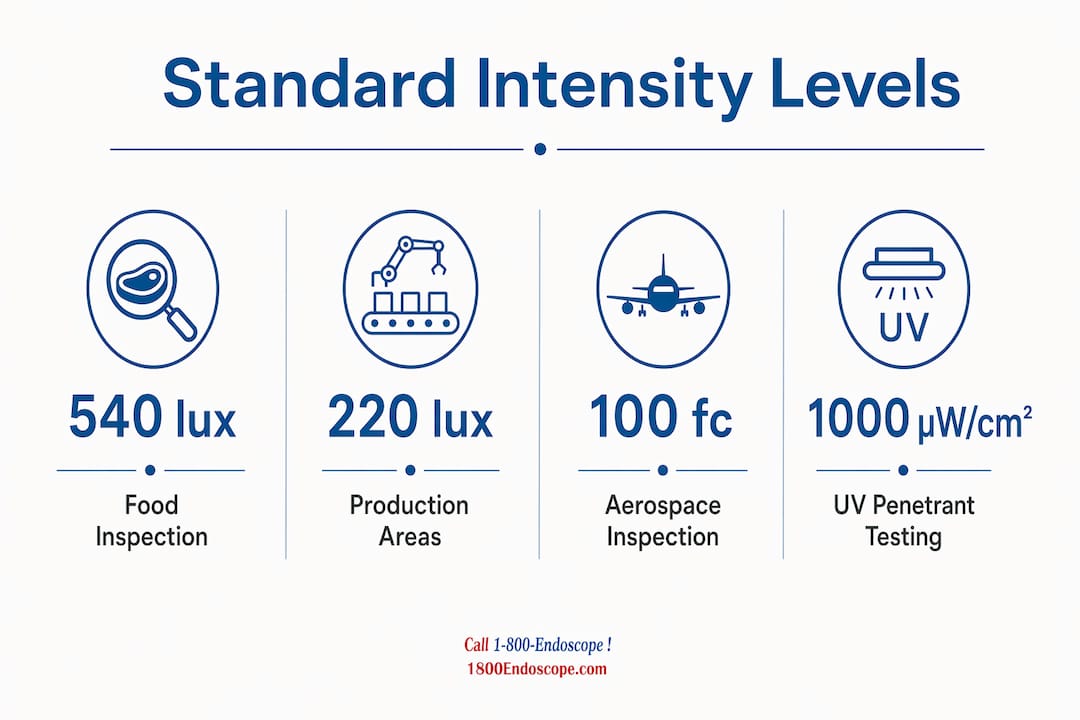
Aerospace inspection is even more demanding. Boeing STP 0637 requires 100 foot-candles at a 45-degree angle, measured at 3 feet from the inspection surface. That angular specification is not arbitrary. It forces the light to rake across the surface, casting shadows from any particulate or surface irregularity that would be invisible under direct overhead illumination.
Fluorescent penetrant testing, a non-destructive testing method used to detect surface cracks in metals and composites, adds a UV dimension. UV intensity must exceed 1,000 µW/cm² for the fluorescent dye to produce visible indication. Below that threshold, the dye fluoresces weakly and shallow cracks go undetected.
| Application | Standard | Minimum Intensity | Measurement Condition |
|---|---|---|---|
| Food inspection surfaces | GFSI | 540 lux | At work surface level |
| Food production areas | GFSI | 220 lux | At work surface level |
| Aerospace surface cleanliness | Boeing STP 0637 | 100 foot-candles | 45° angle, 3 ft from surface |
| Fluorescent penetrant testing | NDT industry practice | 1,000 µW/cm² UV | At inspection surface |
Lux readings must be taken at the work surface, not at ceiling height. A fixture rated at 1,000 lux at the lamp delivers a fraction of that at the inspection point. Calibrated photometers and documented measurement records are required for compliance audits in both food manufacturing and aerospace contexts.
Advanced lighting techniques that go beyond raw intensity
Raw intensity is necessary but not sufficient. The most effective inspection setups combine controlled intensity with deliberate geometry, spectral selection, and in some cases software-defined illumination control.
Dome-based diffuse illumination eliminates specular reflections on shiny metal surfaces by surrounding the target with a uniform light field. No single bright point exists to create a hotspot. The result is a flat, even illumination that lets surface texture and defects appear without interference from the surface's own reflectivity. This technique is standard in machine vision inspection of machined parts and is increasingly applied in veterinary endoscopy for imaging tissue surfaces inside reflective body cavities.
Multi-angle photometric stereo illumination takes this further. By firing light from multiple controlled angles in sequence and combining the resulting images, the system builds a depth map of the surface. Shallow scratches and micro-cracks that are invisible in any single image become apparent in the combined output. Multi-source illumination with AI processing improves steel defect classification accuracy by more than 5%. That gain comes not from brighter light but from smarter light geometry.
Software-defined lighting systems allow technicians to adjust intensity, angle, and spectral output from a single interface. Illumination geometry controls defect visibility on polished surfaces more than intensity alone, because specular reflections can hide flaws even at correct lux levels if the angle is misaligned. Software control eliminates the trial-and-error of repositioning physical fixtures.
Combining UV and visible light expands detection range. Fluorescent penetrant testing uses UV to excite dye trapped in cracks, while visible light inspection confirms surface geometry. Running both in sequence on the same part catches defects that neither method alone would reliably find. 1800endoscope's light sources for endoscopic inspections address this dual-spectrum need in both industrial borescope and veterinary endoscope configurations.
Pro Tip: For inspecting inside tubes, bores, or body cavities, position the light source at a slight offset from the camera axis. Coaxial lighting flattens surface texture. A small angular offset creates the shadow contrast that reveals surface defects.
Common pitfalls in managing light intensity during flaw detection
The most common error in inspection lighting is treating intensity as a dial to turn up until the surface looks bright. That approach produces overlit inspections that generate false negatives at a rate that undermines the entire quality process.
- Excessive intensity: Washed-out images collapse tonal gradients and hide shallow defects. Reduce intensity until surface texture becomes visible, then increase incrementally.
- Uneven coverage: Hot spots from a single point source create false shadows and blind zones. Use multiple fixtures or diffuse sources to achieve uniform coverage across the full inspection area.
- Ambient light contamination: Overhead facility lighting, windows, and reflections from nearby equipment all add uncontrolled intensity that shifts the effective lux level at the inspection surface. Shield the inspection station or measure ambient contribution separately.
- Degraded light sources: UV and LED intensities degrade over time. Scheduled calibration and replacement of light sources is required to maintain consistent inspection conditions. A UV lamp that tested at 1,200 µW/cm² six months ago may now be below the 1,000 µW/cm² threshold without any visible sign of failure.
- Ignoring surface condition: Oil films, dust, and surface coatings change how light interacts with the inspection target. Clean the surface to the inspection standard before setting intensity levels.
The light source calibration process is not a one-time setup task. It is a recurring maintenance requirement that directly determines whether your inspection results are defensible.
Key Takeaways
Light intensity is the primary variable in flaw detection, but correct angle, uniformity, and scheduled calibration determine whether that intensity actually reveals defects or hides them.
| Point | Details |
|---|---|
| Intensity has an upper limit | Excessive brightness causes washout and veiling glare that mask defects and produce false negatives. |
| Standards set the floor | GFSI requires 540 lux at inspection surfaces; Boeing STP 0637 requires 100 foot-candles at 45° for aerospace work. |
| UV intensity is non-negotiable | Fluorescent penetrant testing requires UV intensity above 1,000 µW/cm² for reliable crack detection. |
| Geometry matters as much as brightness | Multi-angle and diffuse illumination reveal defects on reflective surfaces that direct bright light conceals. |
| Calibration is a maintenance task | LED and UV sources degrade over time; scheduled measurement and replacement are required for consistent results. |
What I've learned about light intensity that most guides get wrong
Most inspection guides treat light intensity as a specification to meet and then forget. Set it to 540 lux, check the box, move on. What that approach misses is that intensity is a dynamic variable. The same surface under the same fixture produces different effective illumination depending on the angle of the fixture, the age of the lamp, the cleanliness of the lens, and the ambient light in the room at that moment.
Working with endoscopic inspection systems across both veterinary and industrial applications, the pattern I see repeatedly is that teams invest in high-resolution cameras and then underinvest in the light source. A shadow-free LED borescope with controlled, uniform output consistently outperforms a higher-resolution scope with an aging or poorly positioned light source. The image quality ceiling is set by the light, not the sensor.
The emerging integration of adaptive lighting with AI processing is the development worth watching. Systems that automatically adjust intensity and angle based on surface reflectivity readings are already improving steel defect classification by measurable margins. In veterinary endoscopy, the same principle applies: adaptive illumination that responds to tissue reflectivity in real time will reduce the skill dependency of diagnostic imaging. The technology exists. The adoption curve in both industrial and veterinary settings is just beginning.
— Endoscope
Inspection equipment with built-in lighting control from 1800endoscope
Controlled illumination is only as good as the equipment delivering it. 1800endoscope carries portable endoscope systems and borescopes built for professionals who need adjustable, reliable light output in the field and in the clinic.
The portable airway inspection endoscope from 1800endoscope delivers direct-monitor video with SD card recording in a 6mm diameter system designed for tight-access inspections. For broader industrial applications, the borescope and endoscope catalog covers a full range of lighting configurations suited to NDT work, aerospace inspection, and veterinary diagnostics. Veterinary professionals can also explore the veterinary rigid endoscopy catalog for systems optimized for diagnostic imaging in small and large animals. Every system in the catalog is selected with light output quality as a primary specification, not an afterthought.
FAQ
What is the minimum light intensity for visual inspection?
The minimum depends on the application. GFSI standards require 540 lux at food manufacturing inspection surfaces, while Boeing STP 0637 sets 100 foot-candles at a 45-degree angle for aerospace surface cleanliness inspection.
Can too much light intensity cause missed defects?
Yes. Excessive intensity causes washout and veiling glare that collapse tonal contrast, making shallow cracks and surface irregularities invisible despite the brightness.
What UV intensity is required for penetrant testing?
Fluorescent penetrant testing requires a minimum UV intensity of 1,000 µW/cm² at the inspection surface. Below that threshold, the fluorescent dye does not produce sufficient indication for reliable crack detection.
How often should inspection light sources be calibrated?
Light source calibration is a scheduled maintenance task, not a one-time setup. UV and LED intensities degrade over time, so regular measurement with a calibrated photometer and documented replacement cycles are required to maintain inspection reliability.
Does lighting matter more than camera resolution for defect detection?
Lighting determines defect visibility before the camera records anything. A high-resolution sensor cannot recover contrast that poor illumination never created, making the light source the primary determinant of inspection quality.