
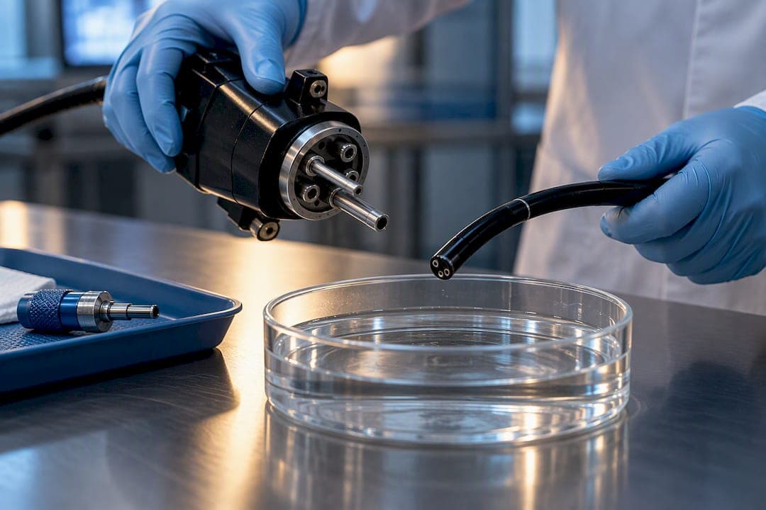
A chip-on-tip endoscope puts a miniature CMOS image sensor directly at the distal end of the probe, replacing the rod-lens relay or fiber bundle that traditional scopes use to carry an image back to a camera. That single change shrinks the shaft diameter, delivers a digital video signal straight from the tip, and cuts the bulk of external camera heads. The trade-off engineers inherit: tighter sealing demands, validated reprocessing, and thermal management packed into a few millimeters of space.
TL;DR:
- CMOS sensors used in chip-on-tip endoscopes are smaller and consume less power than CCDs, enabling shafts under 3 mm in diameter.
- Surgeons and technicians should prioritize seal durability and reprocessing validation over image quality, as moisture ingress is a common failure point.
- Resolution and image performance are best assessed through standardized testing like modulation transfer function with validated low-light SNR and dynamic range measurements.
- Interface choices, such as USB-C or proprietary CCUs, impact workflow integration, cable flexibility, and susceptibility to electromagnetic interference.
- Matching probe diameter to specific clinical applications is crucial, with sub-3 mm for ENT and veterinary uses, and larger sizes for GI procedures requiring working channels.
Table of Contents
- What Makes a Chip on Tip Endoscope Different From Rod-Lens Systems
- Miniaturization and Manufacturing Strategies for Sub-2 mm Tips
- How Do You Measure Imaging Performance on a Distal Sensor?
- Getting the Signal Out: Interfaces, Power, and Workflow Fit
- Sterilization and Reprocessing: What U.S. Standards Actually Require
- Engineering Challenges and How to Design Around Them
- Matching Probe Diameter to the Right Application
- What's Next: Metalenses, Phase Imaging, and Smaller Optics
- Building a Procurement Checklist That Actually Protects You
- What We Prioritize in a Reusable Chip on Tip Design
- Where to Start Browsing Chip-on-Tip and Related Endoscopy Equipment
- Sources
- FAQ
What Makes a Chip on Tip Endoscope Different From Rod-Lens Systems
Rod-lens and fiber-optic endoscopes relay an image through a chain of glass elements or coherent fiber bundles to a camera sitting outside the body, at the proximal end. Every relay lens in that chain adds length, weight, and a chance for light loss or image distortion. Chip-on-tip design skips the relay entirely: the sensor sits right behind the objective lens at the distal tip, and the video signal travels out as digital data over a thin cable instead of as light through glass.
CMOS now rivals CCD sensor quality in most clinical imaging tasks, and it does so with a smaller footprint and lower power draw, which matters enormously when your entire electronics package has to fit inside a tip the diameter of a pencil lead. Sensor technology reviews point to CMOS as the default choice for new distal-sensor designs, largely because CCD architectures need more support circuitry and generate more heat per pixel at comparable resolutions.
Illumination follows the same miniaturization logic. Integrated LEDs or µLEDs mounted at the tip replace the light-guide fibers that older scopes route from a remote xenon or halogen source. That switch improves color rendering and contrast because the light source sits inches from the tissue instead of losing intensity over meters of fiber, but it also means the tip now generates heat that has to go somewhere.
Optics are the third variable. Standard miniature lens stacks (typically three to five elements) balance field of view against depth of field, and every extra element adds assembly cost and failure points. Metalenses, flat optical elements that use nanostructures instead of curved glass, are emerging as an alternative that can shrink the optical path further while adding capabilities standard lenses cannot.
A few reference points worth keeping on your bench notes:
- CMOS sensors used in distal-tip designs commonly run smaller footprints and pull less power than equivalent CCD parts, a direct enabler of sub-3 mm shafts.
- Integrated LED packages eliminate the need for a fiber light guide, freeing up cross-section for sensor cabling or a working channel.
- Lens stack choice directly trades field of view for depth of field. Wider FOV lenses see more tissue but blur at close range faster.
Pro Tip: When comparing sensor datasheets, check pixel size before resolution. A higher megapixel count on a distal sensor often means smaller individual pixels, which can hurt low-light sensitivity even as the marketing number goes up.
Miniaturization and Manufacturing Strategies for Sub-2 mm Tips
Getting a sensor, lens stack, and LED package into a probe under 2 mm in diameter is a manufacturing problem as much as a design one. Micro-molding produces the housing and lens barrels with tolerances measured in microns, and it is the standard approach for high-volume distal tips because injection molding at that scale holds repeatability far better than machining.
Flip-chip assembly, where the sensor die is bonded face-down directly onto a substrate, cuts the wiring footprint compared to traditional wire-bonding and reduces the number of connection points that can fail under repeated flexing. Some manufacturers still use wire-bonding for lower-volume or prototype builds because it is cheaper to tool for, even though it eats more space.
Housing strategy is a real design fork: potted assemblies (filled with epoxy or resin around the electronics) are cheaper and simpler to seal, but they are effectively disposable if a seal fails. Welded metal housings cost more to produce and repair but can survive more reprocessing cycles and, in some designs, allow limited servicing.
Quality control at this scale depends on:
- Visual inspection under magnification for lens alignment and solder joint integrity.
- Borescope inspection of the assembled tip interior before final sealing, catching debris or misalignment invisible from outside.
- Leak testing (pressure decay or dye penetration) to confirm the seal will hold under reprocessing immersion.
- Functional imaging tests comparing captured resolution charts against the sensor's rated performance.
Pro Tip: Build your acceptance criteria around leak testing before functional imaging tests. A tip that images perfectly on the bench but fails a pressure decay test will fail in the field within a handful of reprocessing cycles.
How Do You Measure Imaging Performance on a Distal Sensor?
Resolution claims on a spec sheet mean little without a defined test method. Modulation transfer function (MTF) testing, run against a standard resolution chart at a fixed working distance, gives you a real number for how well the lens and sensor combination resolves fine detail, and it is far more useful than a raw pixel count because it accounts for the whole optical chain, not just the sensor.
Pixel size matters as much as pixel count. A smaller pixel packs more resolution into the same sensor footprint, but each pixel collects less light, which drags down signal-to-noise ratio (SNR) in the low-light conditions typical of body cavities. Dynamic range, the sensor's ability to hold detail in both bright specular reflections and shadowed tissue folds in the same frame, becomes a differentiator once you get past basic resolution comparisons.
Frame rate and latency set the ceiling for what a device can be used for. A diagnostic device doing a slow visual survey can tolerate more latency than a device feeding a live feed during a surgical maneuver, where lag between motion and display can translate directly into a wrong cut.
Engineering acceptance criteria worth setting before you finalize a design:
- MTF measured at a fixed working distance and lighting level, not just a datasheet claim from the sensor vendor.
- SNR and dynamic range specs validated under low-light conditions matching your actual clinical use case, not studio lighting.
- Frame rate and end-to-end latency measured from photon capture to display, including any compression or wireless transmission delay.
- Field of view confirmed at the working distance your procedure actually uses, since FOV numbers on a spec sheet assume a specific distance.
CMOS-based distal sensors have closed most of the quality gap with CCD, according to reviews of current endoscopic imaging technology, which is why CMOS now dominates new chip-on-tip designs across resolution tiers.
Getting the Signal Out: Interfaces, Power, and Workflow Fit
Your interface choice shapes cable flexibility, latency, and how the device fits into an existing OR or clinic workflow. The three common paths are USB-C for direct plug-and-play connection to a laptop or tablet, HDMI for feeding a dedicated monitor, and proprietary camera control units (CCUs) that some manufacturers still use to bundle power delivery, image processing, and light control in one box.
- Confirm cable gauge and flex rating against your minimum bend radius requirement. Thinner cables ease routing through tight working channels but carry less current for LED illumination.
- Test end-to-end latency with your actual display and any compression stage active, not just the sensor's raw output timing.
- Run electromagnetic compatibility (EMC) checks in the actual OR or clinic environment, since electrosurgical units and other equipment can introduce interference a bench test misses.
- Validate the full image pipeline software, from capture through any enhancement algorithm to the final display, as a locked configuration before clinical use.
- Decide early whether you need PACS integration or hospital network compatibility, since retrofitting DICOM output onto a device designed for standalone SD-card recording is a significant redesign.
USB-C devices tend to win on simplicity and cost for point-of-care and veterinary settings. Proprietary CCU systems still lead where a facility needs tight integration with an existing OR video routing setup.
Sterilization and Reprocessing: What U.S. Standards Actually Require
Reusable chip-on-tip endoscopes sold in the United States must follow validated reprocessing procedures consistent with ANSI/AAMI ST91:2021, which covers point-of-use treatment, leak testing, manual cleaning, and high-level disinfection or sterilization steps for flexible and semi-rigid endoscopes. The standard is not optional guidance. It is the reference framework FDA expects manufacturers to design against.
FDA's own reprocessing and labeling guidance tells manufacturers to assume worst-case use conditions, meaning a facility might lose a protective cap or skip a step, and to write instructions for use accordingly. That means flushing instructions, accessory sizing details, and validated cleaning diagrams have to be explicit enough that a technician with no engineering background can follow them correctly every time.
Drying deserves more attention than most IFUs give it. A controlled simulation of duodenoscope reprocessing found that a fast-drying method reduced positive microbial cultures substantially right after decontamination down to a significantly lower rate after drying, in a non-clinical test setup. Moisture left in a channel or seal after disinfection is a genuine failure point, not a formality.
Sealing and validated reprocessing decide clinical adoption more than raw image quality does. A sensor can produce a beautiful picture and still fail if the housing lets moisture reach the electronics after the fortieth sterilization cycle.
Design measures that hold up under repeated cycles:
- Seals rated for the specific sterilant or disinfectant chemistry your facility actually uses, not a generic "chemical resistant" claim.
- Connector materials chosen for repeated wet/dry cycling, since connector corrosion is a common early failure point in field returns.
- Documentation packages for 510(k) submissions and hospital procurement that include validated cleaning protocols, worst-case labeling, and cycle-life data, not just performance specs.
Reference our own step-by-step sterilization walkthrough for a practical breakdown of what a validated reprocessing routine looks like in a working clinic.
Engineering Challenges and How to Design Around Them
Moisture ingress is the failure mode that ends careers of otherwise good tip designs. Every reprocessing cycle is a chance for water to find a microscopic gap in a seal or connector, and once it reaches the sensor or LED driver circuitry, the device is done. Choosing connector types and potting compounds rated for repeated immersion, rather than the cheapest option that passes an initial leak test, pays for itself in warranty claims avoided.

Thermal management gets harder as LEDs get brighter. A tip running at high illumination for a long procedure can fog its own lens from internal condensation if there's no path for heat to escape or no anti-fog coating on the optical window. Industry coverage of chip-on-tip design consistently flags housing integrity and electrical connections, not the sensor itself, as the deciding factor in whether a design survives clinical use.
Mechanical fatigue from repeated bending shows up as slowly degrading image quality long before outright failure, as flex cycles loosen lens alignment inside the tip.
- Use connector geometries that provide strain relief and keep bending away from the distal seal itself.
- Select anti-fog window coatings or active thermal paths for high-illumination designs used in longer procedures.
- Decide up front whether a design is meant to be serviced or replaced, since a fully potted housing can't be reopened for repair.
Pro Tip: If you're evaluating a supplier's prototype, ask for cycle-life data from actual leak testing after repeated reprocessing runs, not just a single pressure test on a fresh unit.
Matching Probe Diameter to the Right Application
Diameter dictates what a chip-on-tip device can realistically do, and the range on the market today runs wide. Trans-nasal shafts commonly start around 2.9 mm, and prototype devices have demonstrated working sensors down to 1.8 mm, while GI-scale scopes run up to sizes that accommodate working channels for biopsy forceps or irrigation.
- Sub-3 mm probes: ENT, veterinary small-animal work, and point-of-care exams where a working channel isn't needed.
- 4 to 8 mm probes: general veterinary bronchoscopy and equine airway inspection, where portability and a direct SD-card or USB recording path matter more than a large working channel.
- 9 to 15 mm probes: GI endoscopy and procedures requiring biopsy forceps, irrigation, or insufflation channels alongside the imaging path.
Chip-on-tip wins at the bedside and in the field precisely because it drops the bulky camera control unit older Hopkins rod-lens systems require. Fiber-based and Hopkins rigid systems still hold ground in high-magnification arthroscopic and otoscopic procedures where optical clarity at very close range, without any digital processing lag, is the priority.
What's Next: Metalenses, Phase Imaging, and Smaller Optics
Metalens research is the clearest signal of where distal-tip optics are headed. Flat lenses built from nanostructured surfaces instead of curved glass can shrink the optical stack and add capabilities standard lenses simply can't deliver in the same footprint. A lab prototype using a metalens with a 0.5 mm aperture achieved single-shot quantitative phase imaging (QPI) with a 28 degree field of view at video rate, entirely without the bulky interferometry hardware QPI traditionally requires.
QPI matters clinically because it can reveal tissue structure and density variations invisible in standard reflectance imaging, without adding a contrast agent or extra procedure step.
- Metalens integration could let future tips add phase-sensitive imaging without growing the shaft diameter.
- µLED arrays and early IR/3D imaging prototypes point toward multimodal tips that combine standard color video with depth or spectral data.
- These capabilities remain lab prototypes today. Expect a multi-year gap before they reach validated, commercially available devices.
Building a Procurement Checklist That Actually Protects You
Before you sign off on a chip-on-tip device, demand documentation on sensor footprint and pixel size, validated IFU reprocessing steps, connector type and cycle-life rating, and expected service life under normal use. On the workflow side, confirm recording format, image export options, and whether the device integrates with your existing OR or PACS setup, or requires standalone software.
Ask suppliers for sample evaluation protocols you can run in-house rather than accepting bench-test claims at face value. Our medical endoscope and accessories catalog and repair and evaluation services are built around exactly this kind of pre-purchase scrutiny, giving procurement teams a path to test before committing budget.
What We Prioritize in a Reusable Chip on Tip Design
Sealing and validated reprocessing come before image quality on our list, because a device that can't survive its intended cycle count is worthless no matter how sharp the picture looks on day one. Portability and ease of service matter almost as much. Clinics adopt what technicians can actually maintain without sending it back to the factory. Test small-diameter prototypes with your own reprocessing routine before you buy in volume, not just on a demo unit under ideal conditions.
— Endoscope
Where to Start Browsing Chip-on-Tip and Related Endoscopy Equipment
Veterinary and point-of-care chip-on-tip systems are priced well below traditional hospital-grade imaging setups, while providing HD imaging and portability suited to day-to-day use in clinics.
Our medical endoscopes and accessories page carries the New Portascope line alongside compatible accessories, and it's a good starting point if you're speccing out a device for a clinic or field team. If your current scope needs evaluation or refurbishment rather than replacement, our repair and equipment services page details available options. Procurement teams evaluating rigid options for arthroscopic or otoscopic work can also browse a rigid scope category directly. Potential buyers can contact through these pages to request spec sheets or inquire about sample unit evaluation before committing to an order.
Sources
- Endoscopic imaging technology today
- Working together to improve reusable medical device reprocessing
FAQ
Do Patients Wake Up During an Endoscopy?
Most diagnostic endoscopy procedures use sedation that keeps patients relaxed but not fully unconscious, so some patients report partial awareness or grogginess rather than a complete blackout. The depth of sedation depends on the procedure and the facility's protocol, and deeper anesthesia is used for more invasive or lengthy procedures.
What Is a Common Diagnosis Found During Endoscopy?
Upper GI endoscopy frequently identifies conditions like acid reflux damage, gastritis, ulcers, and polyps, since the direct visual access a chip-on-tip or fiber-optic scope provides is well suited to catching mucosal changes invisible on imaging scans. Biopsy forceps passed through the working channel let the physician sample suspicious tissue in the same procedure.
What's the Difference Between a Borescope and an Endoscope?
Both use the same core imaging technology, a distal camera or fiber bundle feeding a display, but a borescope is built for industrial inspection of pipes, engines, and mechanical assemblies, while an endoscope is built and validated for use inside living tissue with medical-grade sterilization requirements. Our borescope category covers the industrial and pipe-inspection use case specifically.
Can You Feel a Scope During an Endoscopy?
Patients typically feel pressure or mild discomfort rather than sharp pain, since the scope itself is thin and flexible and the throat or entry point is usually numbed or the patient is sedated. Gagging sensations during upper GI procedures are common and usually brief.
What Diameter Chip-on-Tip Endoscope Do I Need?
Diameter depends entirely on the application: sub-3 mm probes suit ENT and small-animal veterinary work, 4 to 8 mm probes fit general veterinary and equine airway use, and 9 to 15 mm probes accommodate GI procedures needing a working channel for biopsy forceps or irrigation. Matching diameter to your actual procedure, not just picking the smallest available option, is the first filter in any procurement decision.