
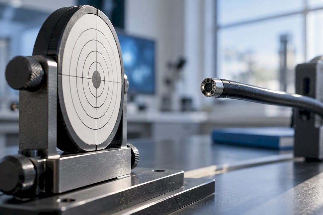
Endoscope field of view (FOV) is the vertex angle of the imaging cone, but which vertex you use, the distal window or the entrance pupil, determines whether a labeled number holds up at your actual working distance. ISO 8600-3 specifies two test methods built around these different vertices, and for short working distances the entrance-pupil method gives the truer result. Published ranges of roughly 90 to 170 degrees are common on spec sheets, but they only mean something once you know which method produced them.
TL;DR:
- Using the correct measurement vertex, either the distal window or entrance pupil, is essential since it significantly impacts the actual field of view at short working distances.
- ISO 8600-3 specifies two measurement methods aligned with these vertices, and choosing the wrong one leads to inflated or inaccurate FOV claims, especially in capsule and chip-on-tip designs.
- FOV calculations rely on D1, D2, r1, and r2 measurements, with shorter working distances and misaligned targets increasing uncertainty and error margins.
- Labeled FOV figures without method and working distance details are unreliable; always verify the measurement approach and test conditions.
- Field of view alone does not determine image quality; assessing modulation transfer function at the intended working distance is critical for practical performance evaluation.
Table of Contents
- Definitions and notation you need before you measure anything
- What ISO 8600-3 specifies and when to use method A vs method B
- Calculating FOV from D1, D2, r1, and r2 with a worked example
- Building a repeatable bench protocol for FOV testing
- Why labeled FOV numbers often overstate real performance
- Why field of view alone doesn't tell you enough
- Checklist for running and reporting your own FOV test
- What matters most when you actually have to choose a scope
- Finding the right endoscope for testing and everyday procedures
- Sources
- FAQ
Definitions and notation you need before you measure anything
FOV is an angular measurement, not a distance. It describes the cone of space the optical system captures, expressed in degrees, and it is easy to confuse with the visible area at a given distance, which grows or shrinks depending on how far the target sits from the lens. Two scopes with identical FOV specifications can produce very different visible circles at 10 mm versus 50 mm, so any comparison needs a stated working distance alongside the angle.
The standard notation used in FOV measurement literature ties directly to physical setup steps:
- D1 and D2 are two known distances from the reference vertex to a test target, typically set with a calibrated stage.
- r1 and r2 are the radii of the visible circle on the target at those two distances, read off a concentric-ring pattern.
- Entrance pupil (EP) is the optical vertex of the imaging cone as light actually converges inside the lens system, often sitting behind the physical tip.
- Distal window surface (WS) is the physical front glass of the scope, easy to locate mechanically but not always where the optical cone truly originates.
The gap between EP and WS matters because it changes where you should be measuring from. Manufacturer literature commonly lists flexible endoscope FOV values between about 90 and 170 degrees, but the PMC review notes that these labels rarely state which vertex or working distance produced them.
What ISO 8600-3 specifies and when to use method A vs method B
ISO 8600-3:2019 is the current edition governing optical performance characterization for medical endoscopes, and it defines field of view along with the test procedures used to measure it. The standard sets out two accepted approaches, and choosing the wrong one for your device geometry is the most common source of inflated FOV claims.
Method A references distances from the distal window surface. It is mechanically simple: you know exactly where the glass tip is, so you can set D1 and D2 with a ruler or calibrated stage without needing any optical modeling. This works well for endoscopes with a conventional lens stack where the entrance pupil sits close to the physical tip, which is common in standard-length rigid and flexible scopes used at moderate working distances.
Method B references distances from the entrance pupil instead. This takes more setup, since locating the EP usually requires either an optical model of the lens assembly or careful bench characterization, but it becomes necessary for chip-on-tip designs, capsule endoscopes, and other close-focus systems where the EP sits noticeably behind the WS. ISO 8600-3:2019 permits either method A or method B, or an equivalent alternative, provided the results are demonstrably comparable.
The single most important reporting habit: state which method you used. A FOV number with no vertex label is not a complete measurement, it is a marketing figure. Every lab report, spec sheet, or comparison table should carry the method designation next to the angle.
- Method A: fast, low-equipment-overhead, appropriate when EP and WS are close together.
- Method B: slower, requires EP location, necessary for short-working-distance and chip-on-tip designs.
- Neither method is universally correct: the choice depends on the optical geometry of the specific scope under test.
Documented distinction: ISO 8600-3:2019 explicitly separates the distal-window method from the entrance-pupil method because using the wrong vertex for a given design produces a measurable, reproducible error rather than random noise.
Calculating FOV from D1, D2, r1, and r2 with a worked example
The formula testers apply under either method is the same geometric relationship, only the reference vertex changes:
FOV = 2 × arctan[(r1 - r2) / (D1 - D2)]
Here, D1 and D2 are two measured distances from the chosen vertex (WS for method A, EP for method B) to a flat target, and r1 and r2 are the radii of the visible image circle on that target at those two distances. The PMC paper documents this geometric derivation as the basis for method A style calculations, and the same triangulation logic applies to method B once D1 and D2 are referenced to the EP instead.
- Mount a concentric-circle target perpendicular to the scope's optical axis on a calibrated linear stage.
- Set the target at distance D1, illuminate evenly, and capture the image, then read the radius r1 where the visible circle intersects the rings.
- Move the target to a second distance D2 and repeat, reading r2 under the same illumination and alignment conditions.
- Plug the four values into the formula to compute the angular FOV.
Say a scope is tested with D1 set at 30 mm and D2 set at 10 mm from the reference vertex, and the visible circle radius measures r1 = 20 mm and r2 = 8 mm at those positions. The calculation runs: (20 - 8) / (30 - 10) = 12 / 20 = 0.6, and arctan(0.6) is about 31 degrees, so FOV = 2 × 31 = 62 degrees. This is an illustrative calculation only, not a claim about any specific device.
Uncertainty creeps in mainly through three channels: misalignment of the target's perpendicularity to the optical axis, off-center positioning of the circle pattern relative to the lens axis, and imprecise radius reading at the ring boundary. Using a rigid alignment jig, centering the target with a laser pointer or crosshair, and averaging multiple radius readings per distance each reduce these errors substantially.

Building a repeatable bench protocol for FOV testing
A consistent lab setup matters more for FOV testing than for most other optical measurements, because small alignment errors compound directly into the arctan calculation.
Equipment list:
- A flat target printed with concentric circles at known radii, mounted on a rigid backing.
- A calibrated linear translation stage capable of sub-millimeter positioning for D1 and D2.
- Collimated or diffuse, evenly distributed illumination to avoid glare that obscures the ring boundary.
- A coupler or capture setup matched to the scope's native output, whether analog video, SD card recording, or direct digital feed.
- Angular measurement software or a calibrated protractor overlay for cross-checking the computed angle against a direct visual estimate.
Measurement workflow:
- Mount the scope in a fixed clamp so the optical axis stays perpendicular to the target plane throughout the test.
- Align the target center to the lens axis using a crosshair or laser reference before taking any images.
- Position the target at D1, capture the image, and record r1 from the visible ring boundary.
- Reposition to D2, capture again, and record r2 under identical illumination.
- Compute FOV using the formula, then repeat the full sequence at least three times to check for drift or misalignment.
For repeatability, run each device through three to five full measurement cycles and average the results, and when comparing multiple units of the same model, sample at least three devices rather than relying on a single unit. Use the manufacturer's specified working distance for D1 and D2 whenever one is published, rather than defaulting to a fixed 50 mm, since a close-focus device tested at 50 mm will not reflect how it performs at the distance it is actually used.
Pro Tip: Run the alignment check twice, once before capture and once after moving the stage, since a stage that drifts even half a millimeter off-axis will skew r1 and r2 enough to shift the computed angle by several degrees.
Why labeled FOV numbers often overstate real performance
The gap between a distal-window measurement (FOVWS) and an entrance-pupil measurement (FOVEP) is not a rounding error. Experimental data shows FOVWS overestimating FOVEP by 12% to 33% at target distances of 16 mm, 9 mm, and 3 mm, with the error growing sharply as the working distance shrinks.

The root cause is geometric: the entrance pupil often sits physically behind the distal window inside the lens barrel, so measuring from the window surface effectively shortens the true optical distance without anyone accounting for it. At long working distances this offset is negligible relative to D1 and D2, but at short distances, the kind typical of capsule endoscopes and chip-on-tip designs, the offset becomes a large fraction of the total distance and the resulting angular error balloons.
Rules of thumb for spotting a risky spec claim:
- A FOV number with no stated method or vertex is a red flag, not a fact.
- A close-focus or capsule device advertising a very wide FOV without a stated working distance deserves a follow-up question.
- Any FOV figure quoted without a working distance should be treated as incomplete.
When evaluating a device, ask the vendor directly which method was used, where the entrance pupil is located relative to the distal window, and what working distance the test target was set at. Vendors that supply ISO 8600-3 method documentation alongside the raw D1/D2/r1/r2 data are giving you something you can actually verify.
Why field of view alone doesn't tell you enough
FOV describes the angular extent of what a scope can see, but it says nothing about how sharp that image stays across the frame. Modulation transfer function (MTF) and its practical implementation, spatial frequency response (SFR), quantify how well fine detail is preserved from the center of the image to its edges, and they are what actually determine whether a wide FOV translates into a usable wide image or a blurry one at the periphery.
Slanted-edge MTF measurement is the standard practical method: a high-contrast angled edge target is imaged, and the transition sharpness across that edge is analyzed to extract a resolution curve at a chosen spatial frequency. An imaging-assembly study describes this slanted-edge approach and shows MTF varying meaningfully across working distances from 5 to 100 mm, with degradation showing up under 10 mm for some assembly methods that lack close-up imaging correction, while laser-focusing assembly approaches held up better across that same 5 to 100 mm range.
- Request MTF or SFR data at the specific working distance you plan to use, not just a single nominal figure.
- Treat a wide FOV claim with no accompanying MTF data as an incomplete spec.
- For tasks that depend on resolving fine detail near the frame edge, edge-region MTF matters more than the headline FOV number.
A scope with a modest FOV and strong edge-to-edge MTF often outperforms a wider-FOV device with soft corners for tasks like foreign-body identification or tissue-margin assessment.
Checklist for running and reporting your own FOV test
Running a defensible FOV test comes down to controlling the same variables every time and documenting them so someone else can reproduce your numbers.
- Confirm which vertex (WS or EP) applies to your device geometry before choosing method A or method B.
- Calibrate your linear stage and verify target perpendicularity with a crosshair or laser reference.
- Set D1 and D2 at the manufacturer's specified working distance when one exists, rather than a fixed default.
- Capture images at both distances under identical, glare-free illumination.
- Read r1 and r2 from the same ring boundary criterion each time to avoid subjective drift.
- Compute FOV with the formula and repeat the cycle at least three times to establish a standard deviation.
- Record an MTF or SFR snapshot at the same working distance if image sharpness is relevant to the application.
- Document every field before filing the result.
A minimal reporting template keeps comparisons honest across devices and vendors:
| Field | What to record |
|---|---|
| Method | ISO 8600-3 Method A or Method B |
| Working distance | D1 and D2 values in millimeters |
| Radii | r1 and r2 in millimeters |
| Computed FOV | Result in degrees |
| Uncertainty | Standard deviation across repeat trials |
| MTF snapshot | Spatial frequency and resulting MTF value at stated working distance |
When comparing two devices, hold the method and working distance constant across both tests. A method A result on one scope is not comparable to a method B result on another, even if both are labeled "FOV." For ongoing quality assurance, sampling three to five units per production batch and re-running the full protocol quarterly catches drift before it reaches the field.
What matters most when you actually have to choose a scope
For clinicians, FOV is only half the picture: a wider angle can trade off against depth of field and tip flexibility, and a scope that is technically wider but harder to steer through tight anatomy often costs more time than it saves. Balancing FOV against handling and depth of field for the specific procedure usually beats chasing the largest labeled angle on the spec sheet.
For engineers and QA teams, the practical rule is to insist on entrance-pupil based data whenever the use case involves short working distances, and to request MTF results measured at that same working distance rather than a generic nominal figure. A vendor that cannot produce D1/D2/r1/r2 data or a method label is asking you to trust a number nobody can verify.
For procurement, the checklist is short: confirm the test method, confirm the working distance, ask for an MTF snapshot relevant to your application, and require that all of it appears in the reporting format before signing off on a purchase.
— Endoscope
Finding the right endoscope for testing and everyday procedures
Once you know what to ask for, sourcing the right instrument gets simpler. 1800endoscope carries medical endoscopes and endoscopic accessories alongside the New Portascope, along with rigid scopes, otoscopes, and flexible biopsy forceps for veterinary practices building out a bench test or a procedure room.
For industrial inspection work, the borescope and videoscope lineup covers monitor-type SD-card videoscopes and portable pipe inspection scopes suited to close-focus applications where entrance-pupil based FOV data matters most.
- Portable, small-diameter videoscopes for bench testing and clinical use.
- Rigid and flexible scopes with accessories for veterinary procedure rooms.
- Industrial borescopes and micro fiber scopes for NDT inspection work.
If you already have vendor-supplied FOV or MTF data and want help matching it against a device configuration, our technical support team can walk through the numbers with you before you commit to a purchase. Browse the full catalog or reach out to get started on a configuration that fits your working distance and application.
This article is general information, not a substitute for advice from a qualified doctor. Consult a qualified healthcare professional about your own circumstances before acting on anything here.
FAQ
How far can you see with an endoscope?
Visible distance depends on the scope's optics and the application, and it is not a fixed number across devices. What matters more for comparison is the angular field of view at a stated working distance, since that determines how much area is visible at any given distance from the tip.
What is D1 and D2 in endoscopy?
D1 and D2 are two distances measured from a reference vertex, either the distal window surface or the entrance pupil, to a test target during FOV measurement. They are paired with the corresponding visible-circle radii r1 and r2 to compute the angular field of view using the standard arctan formula.
What is the typical size range of an endoscopy scope?
Endoscope diameters vary widely by application, and narrower designs around 5.9 mm have been studied specifically for improved patient tolerance in unsedated transnasal procedures compared with standard 9.8 mm scopes. Diagnostic image quality in those comparisons remained comparable between the narrow and standard diameters.
Can you feel a scope during an endoscopy?
Patients undergoing procedures with standard-diameter scopes commonly report more discomfort than those undergoing procedures with narrow-diameter instruments. Clinical comparisons found that narrow-diameter endoscopes improved tolerance for unsedated transnasal exams while keeping diagnostic accuracy comparable to standard scopes.